
Photovoltaic plate installing rack convenient to install

A photovoltaic panel and mounting frame technology, which is applied in the field of solar power generation equipment, can solve the problems of lack of regional versatility and inconvenient connection of photovoltaic panels to photovoltaic panel racks, and achieve the goal of weakening dependence, facilitating transportation, and increasing the adjustable range Effect

Inactive Publication Date: 2015-11-04
SICHUAN LANXUNBAOER ELECTRONICS TECH
View PDF9 Cites 3 Cited by
  • Summary
  • Abstract
  • Description
  • Claims
  • Application Information

AI Technical Summary

Problems solved by technology

[0004] The optimum angle setting for the angle of the photovoltaic panel in the above prior art is affected by the local geographical location, which makes the design of the photovoltaic panel mounting frame in the prior art not regionally universal. At the same time, according to the difference in output power, the existing The photovoltaic panel frame also has the problem of inconvenient connection of photovoltaic panels on the photovoltaic panel frame. The present invention provides a photovoltaic panel mounting frame that is easy to install

Method used


Image

  • Photovoltaic plate installing rack convenient to install
  • Photovoltaic plate installing rack convenient to install
  • Photovoltaic plate installing rack convenient to install

Examples


Embodiment 1

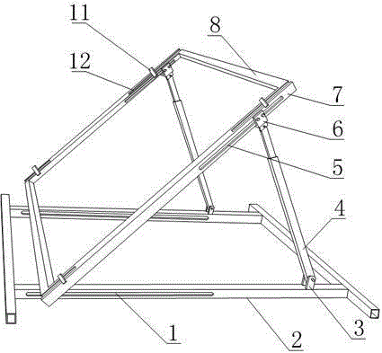
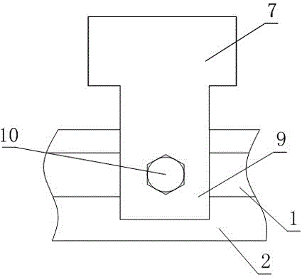
[0032] Such as Figure 1 to Figure 5As shown, a photovoltaic panel mounting frame that is easy to install includes a fixing frame 2 for fixing the mounting frame and a photovoltaic panel fixing plate for fixing the photovoltaic panel. The photovoltaic panel fixing plate is inclined relative to the fixing frame 2, so The photovoltaic panel fixing plate is also fixed with a plurality of buckles 11 for fixing the photovoltaic panel, the fixing frame 2 is provided with a strip-shaped bottom plate chute 1, and the lower end of the photovoltaic panel fixing plate is fixedly connected with a locking plate 9 , the locking plate 9 is provided with a bolt hole, the bolt hole is provided with a locking bolt 10, and the locking bolt 10 is partly located in the bottom plate chute 1;

[0033] The fixed frame 2 is also provided with a hinge block 3, and also includes an adjustment rod 4 for adjusting the inclination of the photovoltaic panel fixing plate. 6. The sliding plate 6 is fixedly c...

Embodiment 2

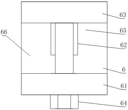
[0037] The present embodiment is further limited on the basis of embodiment 1, as Figure 1 to Figure 3 As shown, the slide plate 6 includes a base 66, a fixed wing 61, a movable wing 63 and an adjustment bolt 64, the fixed wing 61 is fixed on one side of the base 66, and the fixed wing 61 and the movable wing 63 are adjusted Bolts 64 are connected, and a slot 65 is formed between the fixed wing 61 and the movable wing 63 , and the sliding plate 6 is connected to the photovoltaic panel fixing plate through the slot 65 .

[0038] The structure of the above slide 6 is simple, the width of the slot 65 is adjusted by adjusting the bolt 64, and the clamping force of the fixed wing 61 and the movable wing 63 on the fixed plate of the photovoltaic panel is changed to realize the connection and separation of the slide 6 and the fixed plate of the photovoltaic panel. , to achieve the purpose of the invention that the position of the connection point between the sliding plate 6 and the ...

Embodiment 3

[0041] The present embodiment is further limited on the basis of embodiment 1, as Figure 1 to Figure 4 As shown, in order to facilitate the cooling of the photovoltaic panel during use, facilitate the power output of the photovoltaic panel, facilitate the manufacture of the photovoltaic panel fixing plate and the stability of the connection between the photovoltaic panel fixing plate and the fixing frame 2, the photovoltaic panel fixing plate is made of A rectangular frame structure surrounded by two slanting bars 7 and two cross bars 8, the hinge block 3, the adjusting bar 4, and the slide plate 6 are two, and the two slanting bars 7 are provided with a slanting bar groove 5, and the two slanting bars 7 The diagonal rods 7 are respectively connected to the fixed frame 2 through a hinge block 3 , an adjusting rod 4 and a slide plate 6 , and the adjusting bolts 64 are located in the corresponding diagonal rod grooves 5 of the diagonal rods 7 .

[0042] In this embodiment, the ...


PUM


Abstract

The invention discloses a photovoltaic plate installing rack convenient to install. The photovoltaic plate comprises a fixing frame and a photovoltaic plate fixing plate. The photovoltaic plate fixing plate is further fixedly provided with a plurality of buckles. The fixing frame is provided with strip-shaped base plate sliding grooves. The lower end of the photovoltaic plate fixing plate is fixedly connected with locking plates. Each locking plate is provided with a bolt hole. The bolt hole is provided with a locking bolt. The fixing frame is further provided with hinge blocks and adjusting rods. The hinge blocks are hinged with the lower ends of the adjusting rods. The upper ends of the adjusting rods are hinged with sliding plates. The sliding plates are fixedly connected to the photovoltaic plate fixing plate. The buckles comprise pressing plates, fastening sliding blocks and compressing bolts. The photovoltaic plate fixing plate further comprises adjusting grooves. The photovoltaic plate installing rack is simple in structure, and the angle adjustment of a photovoltaic plate relative to a horizontal plane can be realized conveniently; in addition, the photovoltaic plate installing rack depends little on the landform, is convenient to transport and has a good adaptation capability to the size of the photovoltaic plate.

Description

technical field [0001] The invention relates to the field of solar power generation equipment, in particular to a photovoltaic panel mounting frame that is easy to install. Background technique [0002] Conventional energy sources such as coal, oil, and natural gas are increasingly depleted, and there are more and more problems caused by energy shortages in the world. As a clean, pollution-free, inexhaustible energy source, solar energy has played a very important role in the utilization of new energy sources in recent years. Important role, the existing urban street lighting facilities, the solar photovoltaic panel power generation group that has begun to take shape, and even the photovoltaic panels installed on the roof of the family have made outstanding contributions to reducing the dependence of existing production and life on the coal power industry. contribute. [0003] Usually, the fixed photovoltaic panel needs to be set at a certain angle with the horizontal plane...

Claims


Application Information

Patent Timeline
Patent Type & Authority Applications(China)
IPC IPC(8): H02S20/30
CPCY02E10/50
Inventor 李胜峰
Owner SICHUAN LANXUNBAOER ELECTRONICS TECH
Learn More