Distribution-uniform vertical centrifuge

A vertical centrifuge and uniform technology, applied in the field of centrifuges, can solve the problems of high energy consumption, high cost, power consumption, etc., and achieve the effects of uniform cloth, simple structure and low cost

Inactive Publication Date: 2015-11-11
SHUYANG YUZHAN IND CO LTD
View PDF8 Cites 14 Cited by
  • Summary
  • Abstract
  • Description
  • Claims
  • Application Information

AI Technical Summary

Problems solved by technology

[0003] The feeding device used in the existing centrifuge is mostly a pot cover-shaped distribution plate located above the main shaft, or a feeding tube located on the inner side of the drum. When these two feeding devices are used for feeding, the material enters the centrifuge at once. Inside the drum, it will cause a lot of materials to be unevenly distributed, which will cause the centrifuge to appear unbalanced during operation, causing the centrifuge to vibrate
[0004] In recent years, there has been a motor-driven feeder installed on the cover of the centrifuge shell. Although it can spread the material evenly on the drum wall of the centrifuge, it still has the following disadvantages: it needs to consume Electricity; the burden on the shell cover of the centrifuge is increased, and the burden on the shell cover of the centrifuge is already heavy due to the installation of the scraper box, and the installation of the distributor with a motor drive makes the burden on the cover even heavier , when it is necessary to open the cover plate of the shell, it must be assisted by a hydraulic cylinder, which makes the structure of the whole centrifuge more complicated and the cost is higher
In addition, when the existing centrifuge is unloading, the lifting drive mechanism is used to drive the scraper shaft up and down, and the rotary drive mechanism drives the scraper shaft to rotate, which consumes a lot of energy and costs high

Method used


Image

  • Distribution-uniform vertical centrifuge
  • Distribution-uniform vertical centrifuge
  • Distribution-uniform vertical centrifuge

Examples


Embodiment Construction

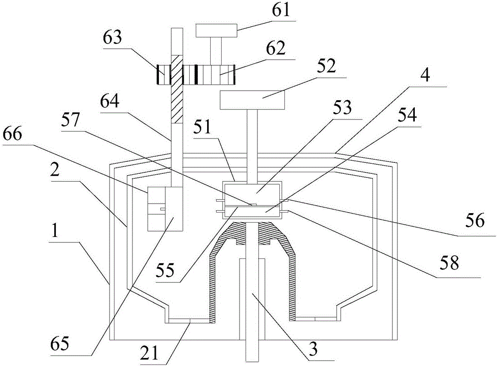
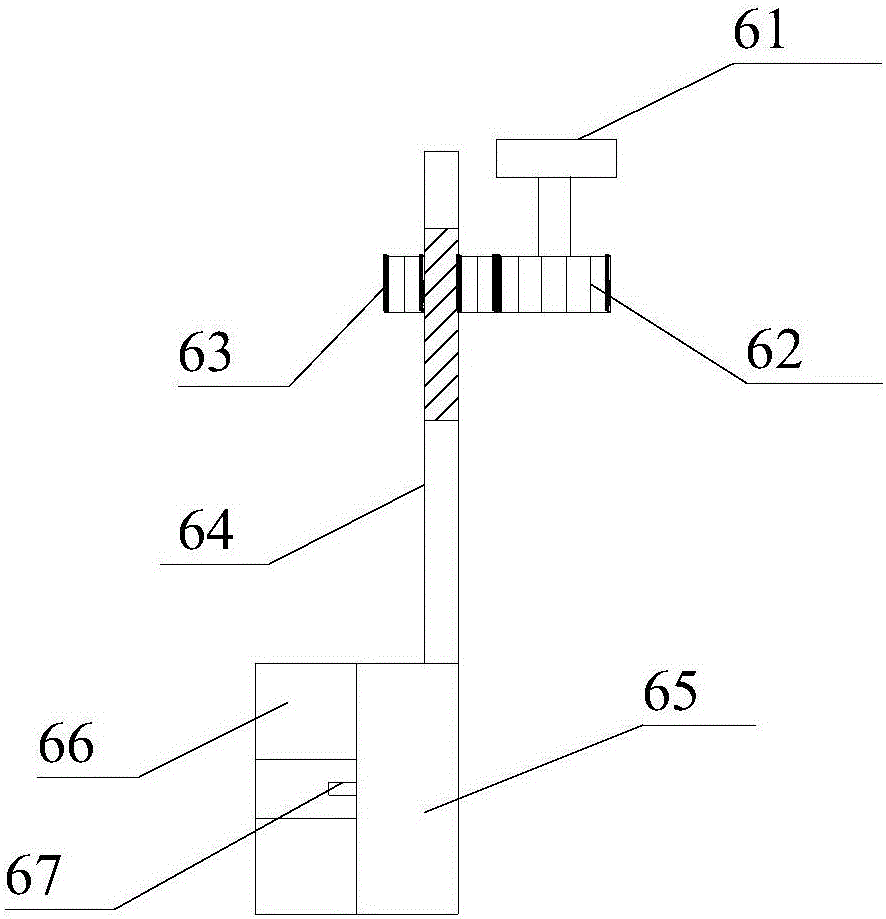
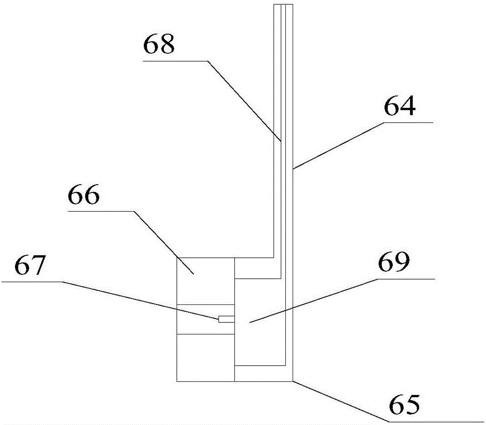
[0020] refer to figure 1 , the present invention proposes a vertical centrifuge with uniform distribution, including a casing 1, a main shaft 3, a drum 2 sleeved on the main shaft 3, a machine cover 4 fixed on the top of the casing 1, a controller, a feeding device, a scraper mechanism for removing solid-phase materials in the drum 2, wherein:

[0021] The bottom of the drum 2 is provided with a discharge port, and the discharge port is provided with a split-type movable door 21, and screen holes are distributed on the movable door 21, and the movable door 21 is connected with the controller. During the rotation of the centrifuge, the residual liquid is discharged out of the drum 2 through the discharge port. The residual liquid may take away part of the solids. A movable door 21 with a sieve hole is arranged at the discharge port to remove the residual liquid. The solid mixed in the residual liquid is filtered out, and after the residual liquid is processed, the controller c...


PUM


Abstract

The invention proposes a distribution-uniform vertical centrifuge. A feeding device comprises a first driving device, and a feeding box arranged in a drum; the feeding box is coaxially arranged with a main shaft, and rotates with the main shaft in opposite directions; a first bin body is arranged in the feeding box; a spraying ring formed by multiple first nozzles is arranged on the side wall of the first bin body in the peripheral direction; first valves are arranged in the first nozzles, and are connected with a controller; and a weight sensor is arranged at the bottom in the first bin body, and is connected with the controller. The distribution-uniform vertical centrifuge feeds raw materials with a preset quantity into the first bin body; the controller controls the opening of the first valves; when the feeding box rotates, the first nozzles spray the raw materials outside the first bin body; the feeding box and the drum relatively rotate; the materials are uniformly dispersed on the inner wall of the drum; the weight sensor detects the weight of the raw materials in the first bin body in real time, and sends the detection result to the controller; and when the detected weight value is equal to the preset weight in the controller, the controller controls the closing of the first valves.

Description

technical field [0001] The invention relates to the technical field of centrifuges, in particular to a vertical centrifuge with uniform cloth distribution. Background technique [0002] A centrifuge is a device that uses the principle of centrifugal separation to separate the suspended material into solid and liquid. A centrifuge has a cylinder, called a bowl, that rotates at high speed about its own axis, usually driven by an electric motor. After the suspension (or emulsion) is added to the drum, it is quickly driven to rotate at the same speed as the drum, and the components are separated under the action of centrifugal force and discharged separately. Generally, the higher the drum speed, the better the separation. [0003] The feeding device used in the existing centrifuge is mostly a pot cover-shaped distribution plate located above the main shaft, or a feeding tube located on the inner side of the drum. When these two feeding devices are used for feeding, the materi...

Claims


Application Information

Patent Timeline
Patent Type & Authority Applications(China)
IPC IPC(8): B04B1/00B04B11/00B04B15/06
Inventor 崔李黄艳
Owner SHUYANG YUZHAN IND CO LTD
Why Eureka
Try Eureka