Hydraulic Forming Technology of Large Radius Cylinder in Dyeing Machine
A forming process and large-radius technology, which is applied in the field of hydraulic forming process of large-radius cylinders of cloth dyeing machines, can solve the problems of increasing the pressure of extruded thin tubes, prone to springback of metal tubes, and incomplete deformation of the transition zone, etc. To achieve the effect of preventing blank damage
- Summary
- Abstract
- Description
- Claims
- Application Information
AI Technical Summary
Problems solved by technology
Method used
Image
Examples
Embodiment 1
[0023] The hydraulic forming process of the large-radius cylinder of the dyeing machine, the process includes the following steps:
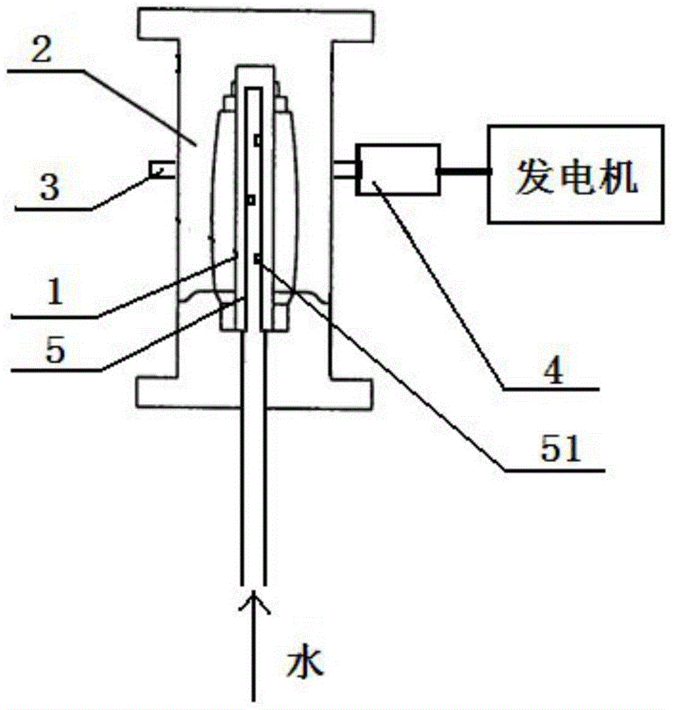
[0024] Step 1: making the plate into a barrel-shaped blank 1 with one end open;
[0025] Step 2: Place the blank 1 in the mold 2;
[0026] Step 3: Inject water into the blank 1 through the open end of the blank 1, and pressurize and bulge the blank 1 through the water;
[0027] Step 4: After the pressure in the blank 1 is stabilized, fill it with water for further pressurization until the blank 1 forms an expanded body according to the mold 2;
[0028] Step 5: Depressurize the water in the expansion body and release the water;
[0029] Step 6: taking out the expanded body after hydroforming from the mold 2;
[0030] Step 7: Polish and polish the expansion body to obtain a large-radius cylinder for the cloth dyeing machine.
Embodiment 2
[0032] Same as Example 1, the difference is that when step 4 is carried out, the pressure inside the blank 1 is stabilized at 400 MPa, and the pressure is kept stable for 12 minutes. Then, the pressure inside the blank 1 is reduced by 35% and kept for 7 minutes, and then the pressure is increased to return to When the pressure value is stable, increase the pressure by 70MPa for secondary pressurization. In the process of keeping the pressure stable, the mold 2 drives the water in the blank 1 to rotate and generate centrifugal force. The water pressurizes the blank 1 through the centrifugal force. The outer surface of the mold 2 is provided with a gear ring 3, and the gear ring 3 is fitted with a gear 4. The gear 4 is driven to rotate by the motor, and the rotation of the mold 2 is realized through the gear ring 3 matched with the gear 4, thereby driving the water in the blank 1 to rotate to generate centrifugal force. It also includes a water injection pipe 5 for injecting wat...
PUM
 Abstract
Description
Claims
Application Information
 - R&D
- Intellectual Property
- Life Sciences
- Materials
- Tech Scout
- Unparalleled Data Quality
- Higher Quality Content
- 60% Fewer Hallucinations
Browse by: Latest US Patents, China's latest patents, Technical Efficacy Thesaurus, Application Domain, Technology Topic, Popular Technical Reports.
© 2025 PatSnap. All rights reserved.Legal|Privacy policy|Modern Slavery Act Transparency Statement|Sitemap|About US| Contact US: help@patsnap.com

