Locking mechanism and locking structure of brake pedal arm and vacuum booster push rod

A locking mechanism and push rod technology, applied in brakes, brake components, transportation and packaging, etc., can solve the problems of difficult processing, small radial projection area, inconvenient positioning, etc., to reduce the risk of worker injury and reduce the number of , the effect of preventing shedding

Active Publication Date: 2018-09-11
ANHUI JIANGHUAI AUTOMOBILE GRP CORP LTD
View PDF8 Cites 0 Cited by
  • Summary
  • Abstract
  • Description
  • Claims
  • Application Information

AI Technical Summary

Problems solved by technology

[0012] The disadvantages of the existing technical solutions are: the radial locking pin hole 3a needs to be processed on the cylindrical locking pin 3, and the radial hole is processed on the cylinder, which is not convenient for positioning, the processing technology is complicated, and the processing is difficult; the locking pin 4 has relatively high rigidity , it is inconvenient to disassemble from the pin hole 3a of the lock pin 3, and there is a sharp point at the lock pin 4a, the worker has the risk of scratching his hands when disassembling; the radial projected area of ​​the lock pin 4 is small, in order to reduce the impact on the locked The U-shaped piece 2b of the vacuum booster push rod assembly 2 is damaged. At the same time, in order to increase the storage capacity of grease and reduce the friction between the contact parts, it is necessary to connect the U-shaped piece 2b of the vacuum booster push rod assembly 2 with the lock. A plastic gasket 5 is added between the pins 4, which increases the number of parts and complicates the structure

Method used


Image

  • Locking mechanism and locking structure of brake pedal arm and vacuum booster push rod
  • Locking mechanism and locking structure of brake pedal arm and vacuum booster push rod
  • Locking mechanism and locking structure of brake pedal arm and vacuum booster push rod

Examples


Embodiment Construction

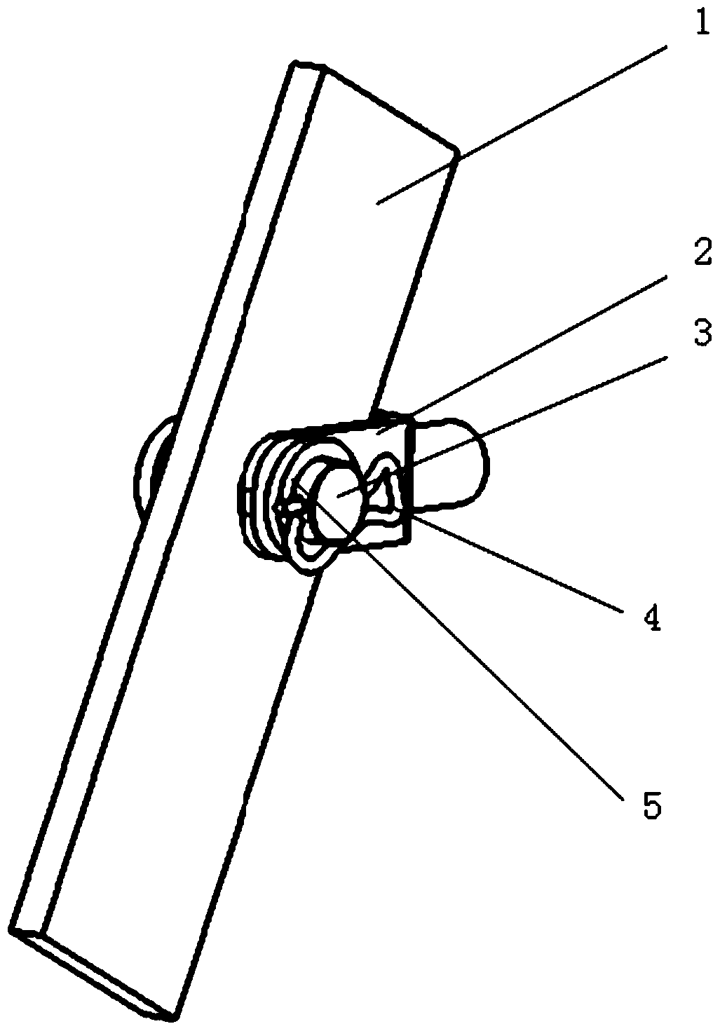
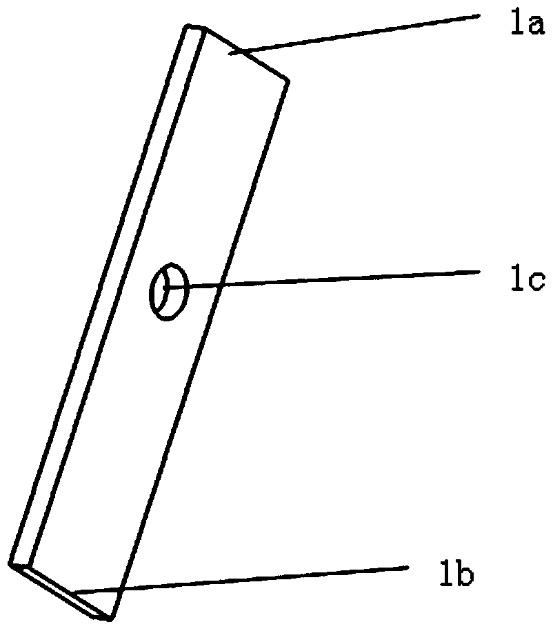
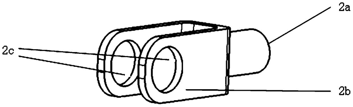
[0038] refer to Figure 7 , The locking structure of the brake pedal arm and the vacuum booster push rod in this embodiment includes the brake pedal arm 1, the vacuum booster push rod assembly 2 and the locking mechanism. Wherein, the structures of the brake pedal arm 1 and the vacuum booster push rod assembly 2 are the same as those described in the background art, and will not be described in detail here. The improvement lies in the locking mechanism, including the locking pin 6 and the locking piece 7 .

[0039] refer to Figure 8 The locking pin 6 used in the locking mechanism of this embodiment has a cap portion 6b and a rod portion 6c, the rod portion 6c is provided with a circumferential ring groove 6a, and the rod portion 6c extends from the ring groove 6a in a direction away from the cap portion 6b. Section 6d. The axial length of end 6d is marked L and the diameter d1. The diameter of the rod portion 6c except the ring groove 6a and the end portion 6d can be the sa...


PUM


Abstract

The invention provides a locking mechanism. The locking mechanism comprises a locking pin and a locking piece, the locking pin is provided with a cap portion and a rod portion, the rod portion is provided with a peripheral ring groove, and the rod portion stretches out of the end in the direction where the ring groove starts to be away from the cap portion starting; the locking piece is provided with a first side wall, a second side wall and a connection wall for connecting the first the side wall and the second side wall, the first side wall and the second side wall are arranged in a spaced mode, the first side wall is provided with a partial big hole and a partial small hole which are communicated with each other, the second side wall is provided with a U-shaped hole and a protruding tongue, the protruding tongue extends from the side, away from the connection wall, of the second side wall into the U-shaped hole in a protruding mode, a gap exists between the protruding tongue and the bottom edge of the U-shaped hole, the side, away from the connection wall, of the second side wall at least reaches the position of the partial big hole, the protruding tongue reaches the position above the partial small hole, the interval between the protruding tongue and the first side wall is smaller than the length of the end, and the diameter of the partial big hole is larger than that of the rod portion and that of the end while the diameter of the partial small hole is smaller than the diameter of the end but larger than the diameter of the ring groove. The invention further provides a locking structure with a brake pedal arm and vacuum booster push rods. The locking mechanism and the locking structure have the advantages of being easy to machine and convenient to disassemble and assemble.

Description

technical field [0001] The invention relates to the field of fasteners, in particular to a locking mechanism and a locking structure of a brake pedal and a vacuum booster push rod. Background technique [0002] Cooperating structures such as pin holes and threads are often used in mechanical engineering. In order to prevent pins from falling off and nuts from loosening, anti-loosening and anti-loosening devices are often installed at the end of the pin and the back of the nut in a locked state. For pin hole matching, a radial pin hole will be opened at the end of the pin, and then the lock pin fastening method will be used to prevent the pin from falling off. Another example is that in automobile manufacturing, in order to prevent the drive shaft nut from loosening, a lock nut is formed by adding nylon material inside the nut. In order to ensure the reliability of work, these anti-loosening and anti-loosening devices are usually difficult to disassemble or can only be used ...

Claims


Application Information

Patent Timeline
Patent Type & Authority Patents(China)
IPC IPC(8): B60T17/00
CPCB60T17/00
Inventor 李鸿飞王光飞孙琼蒋大伟程泽木何小波刘小猛
Owner ANHUI JIANGHUAI AUTOMOBILE GRP CORP LTD
Why Eureka
Try Eureka