Assembly line for removing powder on door/window frame body

A door and window frame and assembly line technology, applied in the direction of cleaning methods, conveyors, cleaning methods and appliances using gas flow, etc., can solve the problems of difficult removal of profiles, harsh working environment, and affecting cleaning effects

Active Publication Date: 2015-11-11
ANHUI KATA DOOR & WINDOW
View PDF6 Cites 6 Cited by
  • Summary
  • Abstract
  • Description
  • Claims
  • Application Information

AI Technical Summary

Problems solved by technology

Grinding is often used to deal with burrs. However, the metal or plastic debris generated during grinding is difficult to remove when adhering to the profile, especially under the static electricity generated by grinding, the debris is even more difficult to handle
[0004] The most commonly used and more efficient methods for cleaning burrs generally include high-pressure water washing or air-jet dust removal. However, in the high-pressure water washing or air-jet dust removal methods, although the manual holding method is flexible in controlling the frame, it is not conducive to personal safety, and the working environment is relatively harsh. It is harsh, and the traditional fixed clamping method is not conducive to the all-round cleaning of the frame, which affects the cleaning effect, and has high requirements for the flexibility of the water spray or air spray device. Therefore, people need a method that can completely clean the frame. Azimuth rotation, and instead of manual holding frame cleaning system

Method used


Image

  • Assembly line for removing powder on door/window frame body
  • Assembly line for removing powder on door/window frame body
  • Assembly line for removing powder on door/window frame body

Examples


Embodiment Construction

[0027] In order to make the technical means and creative features realized by the present invention easy to understand, the present invention will be further elaborated below.

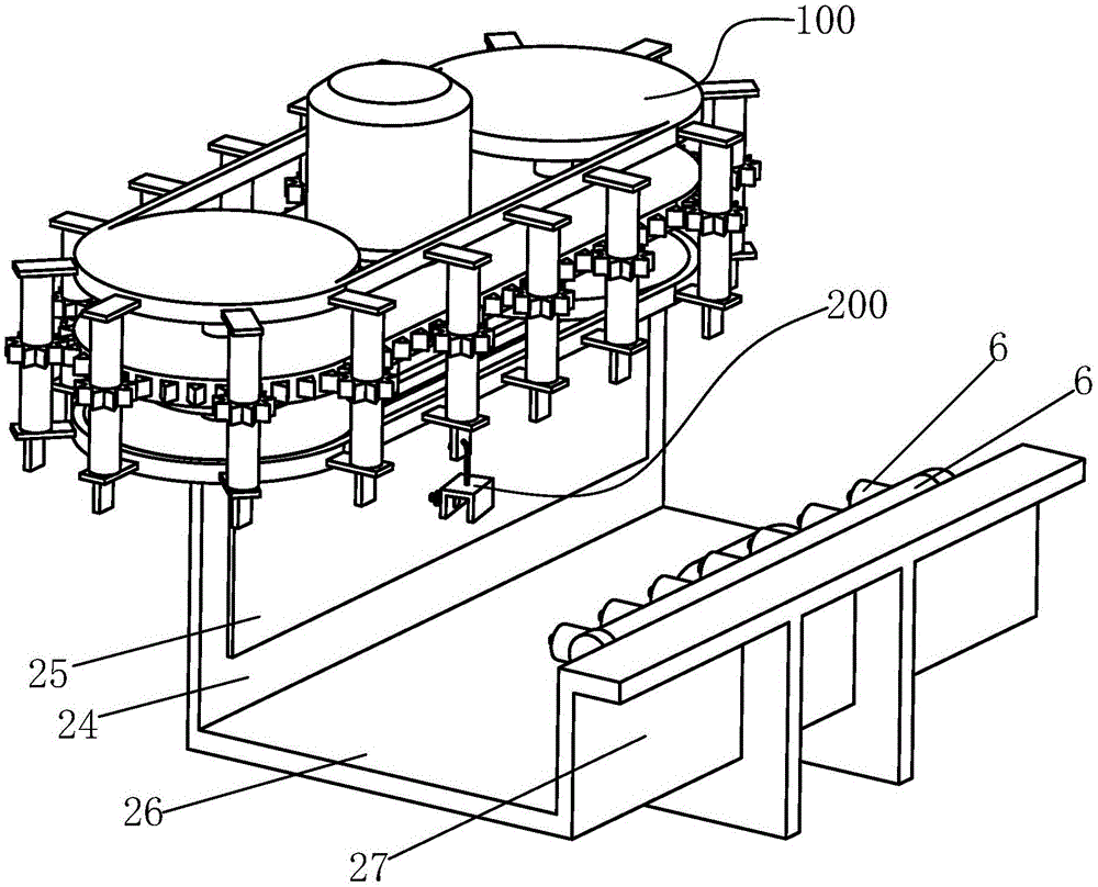
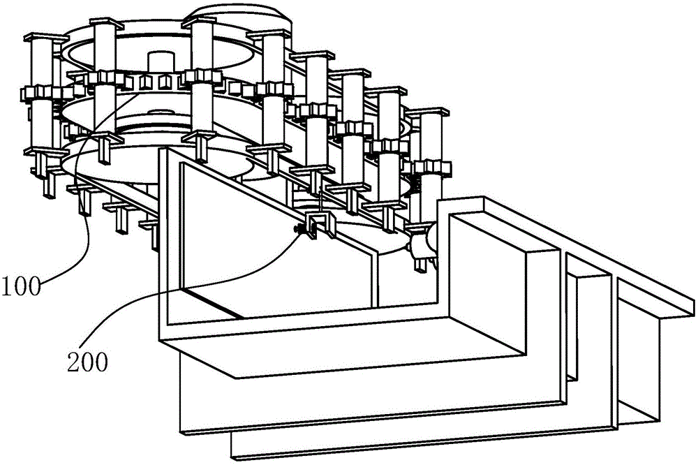
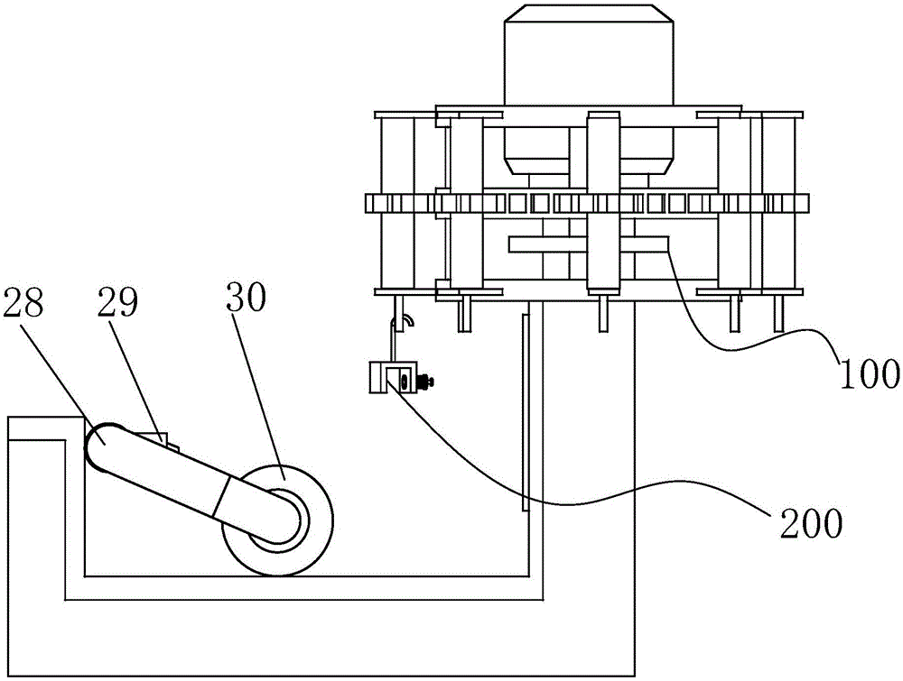
[0028] Such as Figure 1 to Figure 9 As shown, a door and window frame powder removal line includes a suspension device 100. The suspension device 100 includes a waist-shaped base plate 1, and a vertical bar 2 is connected to the left and right sides of the base plate 1 through hinges. The upper ends of the rods 2 are equipped with upper wheels 3, the lower ends of the vertical bars 2 are equipped with lower wheels 4, and the vertical bars 2 are set with driven wheels 5 at positions between the lower wheels 4 and the base plate 1, and the upper end surface of the base plate 1 The middle part is fixed with motor 6, and the shaft of described motor 6 passes through base plate 1 and is connected with driving wheel 7, and described driving wheel 7, driven wheel 5, upper wheel 3 and lower wheel 4 are all sp...


PUM


Abstract

The invention relates to an assembly line for removing powder on a door/window frame body. The assembly line for removing the powder on the door/window frame body comprises a hanging device. The hanging device comprises a kidney-shaped base plate. The left side and the right side of the base plate are each connected with a vertical rod in a hinged mode. Upper wheels are arranged at the upper ends of the vertical rods respectively. Lower wheels are arranged at the lower ends of the vertical rods respectively. The portions, located between the lower wheels and the base plate, of the vertical rods are sleeved with driven wheels respectively. A motor is fixed to the middle of the upper end face of the base plate. A shaft of the motor penetrates through the base plate to be connected with a driving wheel. The driving wheel, the driven wheels, the upper wheels and the lower wheels are all chain wheels. A driving chain is connected between the driving wheel and the driven wheels. An upper special-shaped piece chain is connected between the two upper wheels of the vertical rods. According to the assembly line, rotary columns are controlled by upper connecting pieces and lower connecting pieces to move horizontally around the base plate; in addition, gears on the rotary columns are matched with external teeth and driven by the external teeth to rotate, and accordingly the rotary columns are driven to rotate between the upper connecting pieces and the lower connecting pieces; hanging pieces are fixedly connected with the rotary columns and rotate along with the rotary columns, and thus frame body clamping devices hanging on the hanging pieces are driven to rotate.

Description

technical field [0001] The invention relates to the technical field of door and window processing equipment, in particular to a powder removal line for door and window frames. Background technique [0002] Glass doors and windows are easy to use, low in price, not easy to mold, and easy to maintain, so they are welcomed by more people. Glass doors and windows mainly include glass and a frame stuck around the glass. At present, the frame is mostly made of plastic or aluminum alloy profiles, and the plastic or aluminum alloy profiles are quantitatively cut according to the size of the matched glass. [0003] With the development of cutting equipment and cutting technology and people's diversified demands on glass doors and windows, the number of cutting parts increases, so the burrs left by cutting also increase. Grinding is often used to deal with burrs. However, the metal or plastic debris generated during grinding is difficult to remove when adhering to the profile, especi...

Claims


Application Information

Patent Timeline
Patent Type & Authority Applications(China)
IPC IPC(8): B65G17/20B65G17/26B08B5/02
Inventor 李庭凤
Owner ANHUI KATA DOOR & WINDOW
Why Eureka
Try Eureka