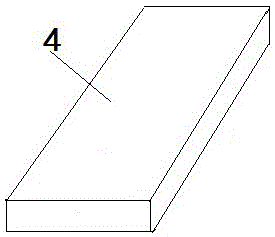
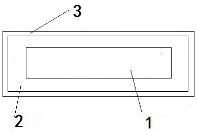
Bumper strip for automotive body
A technology of automobile body and anti-collision strips, which is applied to vehicle parts, transportation and packaging, etc., and can solve the problems of complex processing technology of anti-collision strips and poor anti-collision effects
- Summary
- Abstract
- Description
- Claims
- Application Information
AI Technical Summary
Problems solved by technology
Method used
Image
Examples
Embodiment 1
[0049] An anti-collision strip for an automobile body, the core of which is a particle-reinforced foamed aluminum-based composite material, the core is wrapped with an elastic material layer, and the outer layer of the elastic material is a rectangular steel pipe, which is characterized in that:
[0050] The particle-reinforced foamed aluminum-based composite material is prepared by the following preparation method:
[0051] Prepare an aluminum alloy ingot, its composition percentage is: Mg6﹪, Si1﹪, Sn0.6﹪, Cr0.35﹪, Fe0.65﹪, Ce1.3﹪, Y0.6﹪, Mn0.1﹪, the balance is Al ;
[0052] Melt the above-mentioned aluminum alloy and raise the temperature to 700°C-760°C, pass through protective Ar gas to refine and keep it warm for 10 minutes;
[0053] Add thickener accounting for 6-7% of the total weight of the melt and add silicon carbide and / or alumina particles accounting for 10-12% of the mass fraction of the melt, stir the molten metal at a speed of 500-800rpm for 2-3 minutes, and the...
Embodiment 2
[0065] An anti-collision strip for an automobile body, the core of which is a particle-reinforced foamed aluminum-based composite material, the core is wrapped with an elastic material layer, and the outer layer of the elastic material is a rectangular steel pipe, which is characterized in that:
[0066] The particle-reinforced foamed aluminum-based composite material is prepared by the following preparation method:
[0067] Prepare an aluminum alloy ingot, its composition percentage is: Mg7﹪, Si2﹪, Sn1.2﹪, Cr0.6﹪, Fe0.65﹪, Ce1.5﹪, Y0.8﹪, Mn0.4﹪, the balance is Al ;
[0068] Melt the above-mentioned aluminum alloy and raise the temperature to 700°C-760°C, pass through protective Ar gas to refine and keep it warm for 10 minutes;
[0069] Add thickener accounting for 6-7% of the total weight of the melt and add silicon carbide and / or alumina particles accounting for 10-12% of the mass fraction of the melt, stir the molten metal at a speed of 500-800rpm for 2-3 minutes, and then...
Embodiment 3
[0081] An anti-collision strip for an automobile body, the core of which is a particle-reinforced foamed aluminum-based composite material, the core is wrapped with an elastic material layer, and the outer layer of the elastic material is a rectangular steel pipe, which is characterized in that:
[0082] The particle-reinforced foamed aluminum-based composite material is prepared by the following preparation method:
[0083] Prepare the aluminum alloy ingot, its composition percentage is: Mg6.5﹪, Si1.5﹪, Sn0.9﹪, Cr0.5﹪, Fe0.65﹪, Ce1.4﹪, Y0.7﹪, Mn0.3﹪, The balance is Al;
[0084] Melt the above-mentioned aluminum alloy and raise the temperature to 700°C-760°C, pass through protective Ar gas to refine and keep it warm for 10 minutes;
[0085] Add thickener accounting for 6-7% of the total weight of the melt and add silicon carbide and / or alumina particles accounting for 10-12% of the mass fraction of the melt, stir the molten metal at a speed of 500-800rpm for 2-3 minutes, and ...
PUM
| Property | Measurement | Unit |
|---|---|---|
| particle diameter | aaaaa | aaaaa |
Abstract
Description
Claims
Application Information
 - R&D
- Intellectual Property
- Life Sciences
- Materials
- Tech Scout
- Unparalleled Data Quality
- Higher Quality Content
- 60% Fewer Hallucinations
Browse by: Latest US Patents, China's latest patents, Technical Efficacy Thesaurus, Application Domain, Technology Topic, Popular Technical Reports.
© 2025 PatSnap. All rights reserved.Legal|Privacy policy|Modern Slavery Act Transparency Statement|Sitemap|About US| Contact US: help@patsnap.com


