Fixing assembly for mask plate

A technology for fixing components and masks, applied in ion implantation plating, metal material coating process, coating and other directions, can solve the problems of solid film shape difference, deformation and other problems, to reduce the degree of deformation, easy to manufacture, safe to use reliable results

Active Publication Date: 2015-11-11
TCL CHINA STAR OPTOELECTRONICS TECH CO LTD
View PDF7 Cites 37 Cited by
  • Summary
  • Abstract
  • Description
  • Claims
  • Application Information

AI Technical Summary

Problems solved by technology

Although the existing fixed frame can firmly fix the mask plate, the part of the mask plate located in the evaporation area of ​​the fixed frame (ie, the hollow area of ​​the frame) can also be deformed, resulting in the formation of a solid film formed after the evaporation is completed. There is a difference in shape from the expected shape, especially with large OLED sizes

Method used


Image

  • Fixing assembly for mask plate
  • Fixing assembly for mask plate
  • Fixing assembly for mask plate

Examples


Embodiment Construction

[0024] The present invention will be further described below in conjunction with accompanying drawing.

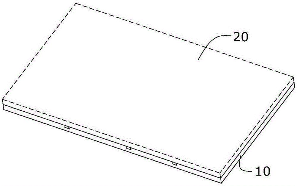
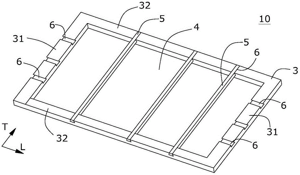
[0025] figure 1 Shows a mask plate fixing assembly 10 and a mask plate 20 according to an embodiment of the present invention, figure 2 A mask plate fixing assembly 10 according to an embodiment of the present invention is shown alone. like figure 1 and figure 2 As shown, the fixture assembly 10 comprises a frame 3 with a hollow vapor deposition area 4 . The frame 3 can be made of stainless steel or nickel-iron alloy material so as to be suitable for harsh conditions during evaporation. The shape of the frame 3 can be a circular frame, a rectangular frame or other polygonal frames. During the manufacturing process, a matching frame 3 is selected according to the shape of the prefabricated display. Normally, the frame 3 is basically the same shape and size as the prefabricated display screen.

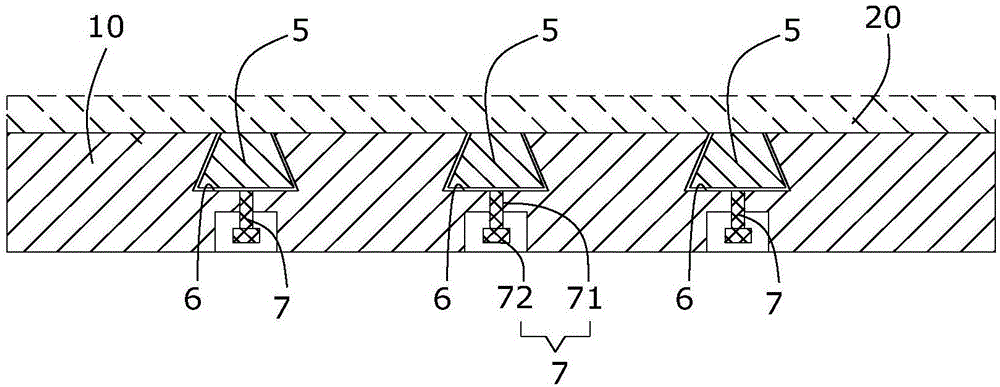
[0026] The frame 3 is used to fix the mask plate 20 covering the vapor d...


PUM


Abstract

The invention relates to a fixing assembly for a mask plate. The fixing assembly comprises a frame with an evaporation area. The frame is used for fixing the mask plate covering the evaporation area, and supporting strips which are detachably arranged on the frame and penetrate through the evaporation area to be used for supporting the mask plate. According to the fixing assembly for the mask plate, the deformation degree of the mask plate can be reduced, and the shape of a solid thin film formed after evaporation is completed is promoted to be nearly consistent with an expected shape.

Description

technical field [0001] The invention relates to an indispensable auxiliary component in the manufacturing process of an organic light emitting display (OLED, Organic Light Emitting Display), in particular to a fixing component of a mask plate. Background technique [0002] In the OLED manufacturing process, the formation of organic thin films requires the use of vacuum evaporation technology. Specifically, in the vacuum evaporation technology, it is necessary to rely on the mask to block a part of the vapor flow (film-forming material molecules or film-forming material molecular atoms), so that the other part of the vapor flow passes through the evaporation holes of the mask and enters the The surface of the plated object (such as a substrate), thereby forming a solid film with a specific pattern on the surface of the object to be plated. [0003] The thickness of the mask plate (usually 30 μm-100 μm) is relatively thin, and the evaporation process is prone to deformation, ...

Claims


Application Information

Patent Timeline
Patent Type & Authority Applications(China)
IPC IPC(8): C23C14/04
Inventor 邹成
Owner TCL CHINA STAR OPTOELECTRONICS TECH CO LTD
Why Eureka
Try Eureka