Movable upward raise boring machine

A raise drilling rig, mobile technology, applied in the field of mining machinery, can solve the problems of unsatisfactory drilling construction, increase construction difficulty, increase mining cost, etc., and achieve the effect of solving the difficulty of large-scale machinery transportation, reducing construction steps, and reducing construction difficulty

Inactive Publication Date: 2015-11-11
BEIJING CHINA COAL MINE ENG CO LTD
View PDF5 Cites 14 Cited by
  • Summary
  • Abstract
  • Description
  • Claims
  • Application Information

AI Technical Summary

Problems solved by technology

However, the existing raise drilling rigs are only suitable for top-down drilling construction, and cannot meet the requirements of drilling from the existing tunnel to the rock formation above the tunnel, nor can it meet the bottom-up operation of the rock formation above the ground. This makes it more difficult to drill rock mass or mines located at higher altitudes from lower altitudes. If the existing raise drilling rig is used, it is necessary to move the raise drilling rig to a higher altitude. This not only increases the difficulty of construction, but also increases the mining cost and reduces the profit when the mine is close to the top of the tunnel or at a lower altitude, using the existing raise drilling rig

Method used


Image

  • Movable upward raise boring machine
  • Movable upward raise boring machine
  • Movable upward raise boring machine

Examples


Embodiment 1

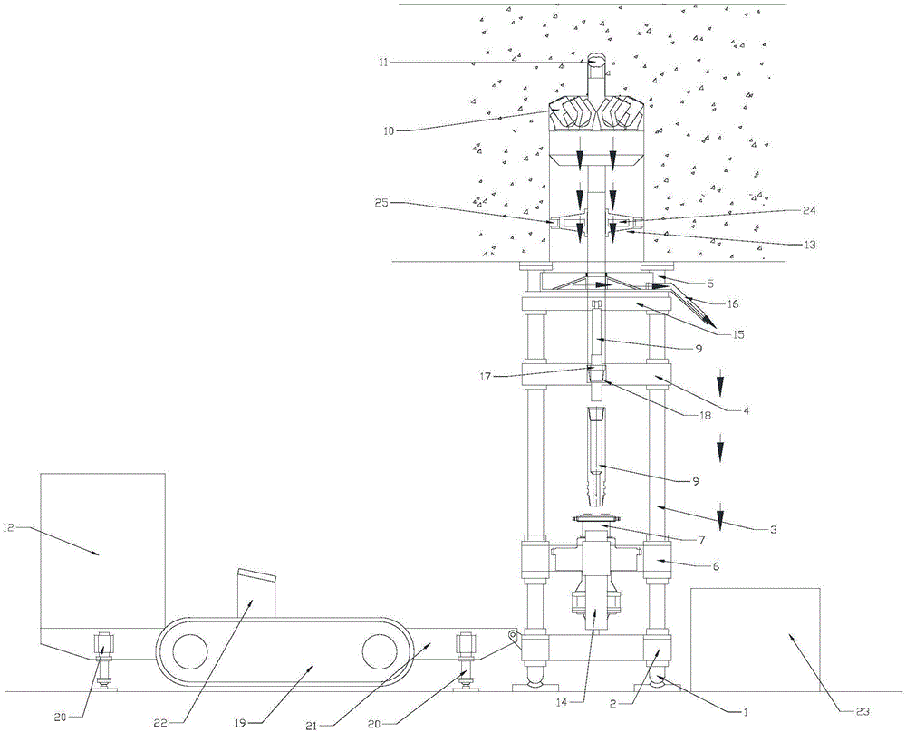
[0032] Such as Figure 1~3 As shown, the mobile upward raising drilling rig of the present invention includes a drilling rig support mechanism, a main thrust cylinder 6, a power head 7 and a drilling tool. The drilling rig support mechanism includes a lower support 1, a base 2, a guide column 3, a top beam 4 and Upper support 5; the upper end of the lower support 1 is fixedly connected to the lower end of the guide column 3, and the upper end of the guide column 3 is fixedly connected to the lower end of the upper support 5; the base 2 is installed near the guide On the guide column 3 at the lower end of the column 3, the top beam 4 is installed on the guide column 3 close to the upper end of the guide column 3, and the main push cylinder 6 is installed between the base 2 and the On the guide column 3 between the top beams 4, the main push cylinder 6 can slide along the guide column 3; the telescopic part 14 of the main push cylinder 6 is fixedly connected with the base 2, and...

Embodiment 2

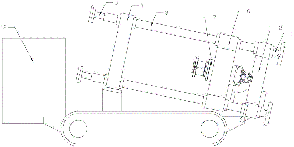
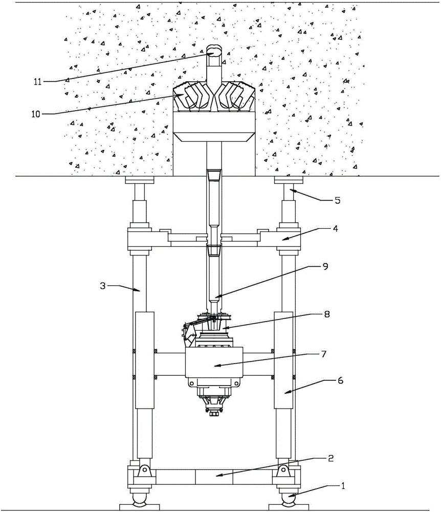
[0038] Such as Figure 4-9 As shown, the mobile upward drilling rig of the present invention includes a drilling device and a moving device.

[0039] Wherein, the drilling device includes a drilling rig support mechanism, a main thrust cylinder 6, a power head 7 and a drilling tool, and the drilling rig support mechanism includes a lower support 1, a base 2, a guide column 3, a top beam 4 and an upper support 5; The upper end of the support 1 is fixedly connected with the lower end of the guide column 3, and the upper end of the guide column 3 is fixedly connected with the lower end of the upper support 5; On the guide column 3, the top beam 4 is installed on the guide column 3 adjacent to the upper end of the guide column 3, and the main push cylinder 6 is installed on the top beam 4 between the base 2 and the top beam 4. On the guide column 3, the main thrust cylinder 6 can slide along the guide column 3; the telescopic part 14 of the main thrust cylinder 6 is fixedly conne...


PUM


Abstract

The invention discloses a movable upward raise boring machine. The movable upward raise boring machine comprises a machine supporting mechanism, a main thrust oil cylinder, a power head, a crawler type traveling portion and a drilling rig, wherein the machine supporting mechanism comprises a lower support, a base, a guiding column, a top beam and an upper support; the upper end of the lower support is fixedly connected with the bottom surface of the base; the top surface of the base is fixedly connected with the lower end of the guiding column; the upper end of the guiding column is fixedly connected with the bottom surface of the top beam; the top surface of the top beam is fixedly connected with the lower end of the upper support; the top surface of the base is hinged to the main thrust oil cylinder; a retractable portion of the main thrust oil cylinder is fixedly connected with the power head; and the power head is slidably connected with the guiding column and is in transmission connection with the drilling rig. Well drilling construction can be performed from bottom to top, requirements of well drilling construction in the existing underground tunnel on a rock formation or a formation positioned below the underground tunnel are met, and requirements of well drilling construction on a rock formation or a formation above the underground tunnel can also be met.

Description

technical field [0001] The invention relates to the field of mining machinery, in particular to a mobile upward raising drilling machine. Background technique [0002] The technical principle of the raise drilling rig is that the motor of the drilling rig drives the hydraulic pump, the hydraulic pump drives the hydraulic motor, and drives the power head, and uses the hydraulic power to transmit the torque to the drilling tool system, driving the drill pipe and the drill bit to rotate, the pilot hole drill bit or the reaming drill bit Under the action of drilling pressure, the upper hob performs pure rolling or slight slip along the rock working face at the bottom of the well. At the same time, the axial tension and pressure generated by the oil cylinder of the main engine also act on the pilot hole drill bit or the reaming drill bit through the power head and drill rod, so that the hob of the pilot hole drill bit rolls under the action of drilling pressure, resulting in impa...

Claims


Application Information

Patent Timeline
Patent Type & Authority Applications(China)
IPC IPC(8): E21B7/02E21B15/00E21B7/28E21B19/10E21B17/10E21B21/01
Inventor 王强刘志强谭杰左永江王桦宁方波韩博邵方圆郭鲁川
Owner BEIJING CHINA COAL MINE ENG CO LTD
Why Eureka
Try Eureka