Combined cycle energy supply system

A combined cycle and energy supply technology, applied in the fields of power, refrigeration and heat pump, can solve problems such as difficulty in utilizing heat energy, unreasonable utilization of temperature difference, and inability to utilize large temperature difference.

Active Publication Date: 2015-11-11
李华玉
View PDF4 Cites 6 Cited by
  • Summary
  • Abstract
  • Description
  • Claims
  • Application Information

AI Technical Summary

Problems solved by technology

[0002] In the system where fuel is used for heating by combustion, there is a large temperature difference between the gas formed by combustion and the heated medium; There is also a large temperature difference; in a distributed energy system powered by a steam power plant, power supply is actually a restrictive additional condition, and there are still situations where the temperature difference cannot be fully utilized in many cases
These situations that cannot realize efficient utilization of thermal energy can be mainly summarized into six aspects: ①Under the condition of no power load, there is a large unusable temperature difference between the gas and the heated medium, which cannot realize efficient utilization of thermal energy; ②Absorption heat pump is equipped , due to the limitation of the working temperature range of the absorption heat pump working medium, there is a large temperature difference between the driving gas and the absorption heat pump working medium, and the use of the temperature difference is unreasonable; There is a large temperature difference; in this way, when using steam to drive the absorption heat pump, the use of temperature difference is unreasonable; ④Lack of low-temperature heat resources, it is difficult to use the heat energy in the environment; ⑤When the temperature of low-temperature heat resources is very low, it is impossible to find a suitable absorption heat pump device The working medium with satisfactory thermal performance and safety performance; ⑥ It is difficult to achieve efficient heating or cooling in the low-temperature section of gas

Method used


Image

  • Combined cycle energy supply system
  • Combined cycle energy supply system
  • Combined cycle energy supply system

Examples


Embodiment Construction

[0086] The first thing to explain is that in the expression of the structure and process, it will not be repeated if it is not necessary; the obvious process will not be expressed. The present invention will be described in detail below in conjunction with the accompanying drawings and examples.

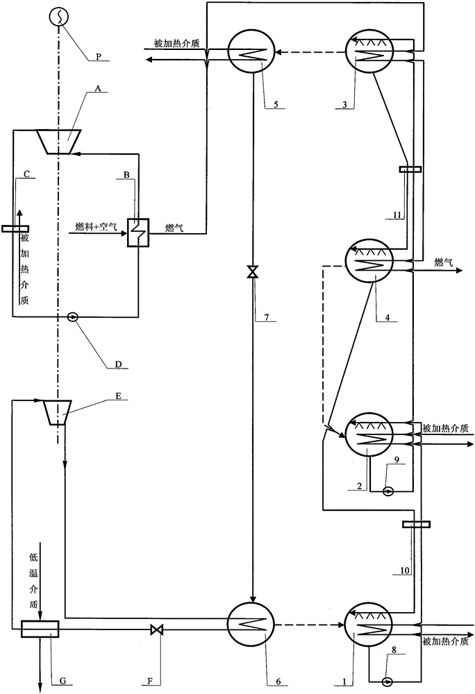
[0087] figure 1 The combined cycle energy supply system shown is realized as follows:

[0088] (1) Structurally, it mainly consists of turbine, boiler, heat exchanger, circulating pump, compressor, low temperature throttle valve, low temperature heat exchanger, absorber, second absorber, generator, second generator, condensation evaporator, throttle valve, solution pump, second solution pump, solution heat exchanger, second solution heat exchanger and working machine; turbine A has a low-pressure steam channel connected to heat exchanger C, heat exchanger C also has a condensate pipeline connected to boiler B via circulating pump D, boiler B also has high-pressure steam channels co...


PUM


Abstract

The invention provides a combined cycle energy supply system and belongs to the technical field of heat energy utilization and heat pumps. A steam power device positive cycle system is formed by a turbine, a boiler, a heat exchanger and a circulating pump. A compression type reverse cycle system is formed by a compressor, a cooler, an expander, a low-temperature heat exchanger and a heat regenerator. An absorption type reverse cycle system is composed of an absorber, a second absorber, a generator, a second generator, a condenser, an evaporator, a throttling valve, a solution pump, a second solution pump, a solution heat exchanger and a second solution heat exchanger. The steam power device positive cycle supplies power to the compression type reverse cycle and supplies drive heat loads to the absorption type reverse cycle. The compression type reverse cycle acquires low-temperature heat loads and supplies heat through the cooler. The absorption type reverse cycle acquires low-temperature heat loads and supplies heat through the absorber, the second absorber and the condenser. Thus, the combined cycle heat supply system is formed.

Description

Technical field: [0001] The invention belongs to the technical field of power, refrigeration and heat pump. Background technique: [0002] In the system where fuel is used for heating by combustion, there is a large temperature difference between the gas formed by combustion and the heated medium; There is also a large temperature difference; in a distributed energy system powered by a steam power plant, power supply is actually a restrictive additional condition, and there are still situations where the temperature difference cannot be fully utilized in many cases. These situations that cannot realize efficient utilization of thermal energy can be mainly summarized into six aspects: ①Under the condition of no power load, there is a large unusable temperature difference between the gas and the heated medium, which cannot realize efficient utilization of thermal energy; ②Absorption heat pump is equipped , due to the limitation of the working temperature range of the absorpti...

Claims


Application Information

Patent Timeline
Patent Type & Authority Applications(China)
IPC IPC(8): F01K11/02F01K17/02F25B25/02F25B1/10F25B41/06F25B29/00F25B41/31
Inventor 李华玉
Owner 李华玉
Why Eureka
Try Eureka