
Solar streetlamp high in solar energy utilization efficiency

A solar street lamp and utilization technology, applied in the field of solar energy equipment and solar street lamps, can solve the problems of low utilization rate of resources and affect the utilization rate of solar energy, and achieve the effect of improving utilization rate of solar energy, improving independence, and ensuring normal work.

Inactive Publication Date: 2015-11-11
JIAXING AOLIFU PHOTOVOLTAIC TECH CO LTD
View PDF5 Cites 7 Cited by
  • Summary
  • Abstract
  • Description
  • Claims
  • Application Information

AI Technical Summary

Problems solved by technology

[0002] Solar street lights use sunlight as energy, solar panels charge the battery during the day, and the battery supplies power to the light source at night, without complicated and expensive pipeline laying, the layout of the lamps can be adjusted arbitrarily, safe, energy-saving and pollution-free, stable and reliable without manual operation, saving Electricity maintenance-free, at the same time, each solar street light is a cycle, so there is no need to worry about the circuit of ordinary street lights being broken and the whole is not bright, but the solar panels in the existing technology are all fixed, and the sun will slowly fade over time. Changing the direction of sunlight reduces the sunlight absorbed by the solar photovoltaic panels, which affects the utilization rate of solar energy, and can only use solar energy as an energy source, and the resource utilization rate is not high

Method used


Image

  • Solar streetlamp high in solar energy utilization efficiency
  • Solar streetlamp high in solar energy utilization efficiency
  • Solar streetlamp high in solar energy utilization efficiency

Examples


Embodiment Construction

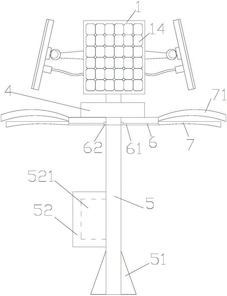
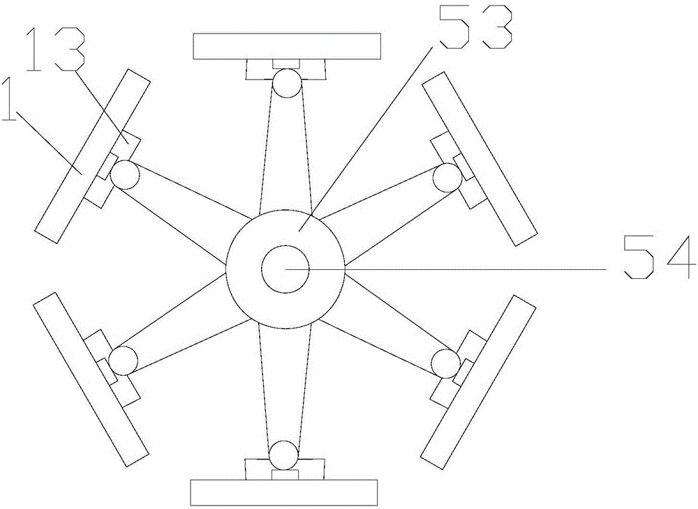
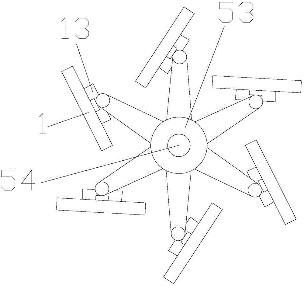
[0017] refer to figure 1 , figure 2 , image 3 and Figure 4 , the present invention is a kind of solar street light with high solar energy utilization rate, comprising solar panel 1, rotating ball 2, support device 3, generator 4, lamp pole 5, connecting rod 6 and lamp tube 7, and connecting rod 5 is installed with connecting Rod 6, lamp tube 7 is installed on the connecting rod 6, generator 4 and rotating disc 53 are installed successively on the lamp rod 5 above connecting rod 6, generator 4 is connected with rotating disc 53 by rotating shaft 54, and rotating disc 53 can Rotation is installed on the light pole 5, and several solar panels 1 are installed on the rotating disk 53. The solar panel 1 also includes an induction receiving device 12, and the induction receiving device 12 is located at the bottom middle of the solar panel 1. The rotating ball 2 is fixedly connected with the induction receiving device 12, one end of the rotating ball 2 is connected with the supp...


PUM


Abstract

The invention provides a solar streetlamp high in solar energy utilization efficiency. The solar streetlamp comprises solar cell panels, rotating balls, supporting devices, an electric generator, a lamp pole, a communicating rod and a modulator tube. The communicating rod is arranged on the lamp pole and provided with the modulator tube. The electric generator and a rotating plate are sequentially arranged on the portion, above the communicating rod, of the lamp pole. The electric generator is connected with the rotating plate through a rotating shaft. The rotating plate is arranged on the lamp pole in a rotatable mode. The solar cell panels are arranged on the rotating plate. The solar streetlamp can automatically rotate according to the irradiation directions of sunlight, and therefore it is ensured that the exposure rate of the sunlight is the maximum, and the solar energy utilization efficiency is obviously improved; meanwhile, wind power can be used for generating electricity, and therefore normal work of the streetlamp is ensured, and economic benefits are improved; in addition, the height of an electricity storage chamber is designed according to the body mechanics principle, and therefore pedestrians can sit on the electricity storage chamber to have a rest; the outer surface of the electricity storage chamber is made of insulating materials, and therefore safety is ensured.

Description

【Technical field】 [0001] The invention relates to the technical field of solar energy equipment, in particular to the technical field of a solar street lamp with high utilization rate of solar energy. 【Background technique】 [0002] Solar street lights use sunlight as energy, solar panels charge the battery during the day, and the battery supplies power to the light source at night, without complicated and expensive pipeline laying, the layout of the lamps can be adjusted arbitrarily, safe, energy-saving and pollution-free, stable and reliable without manual operation, saving Electricity maintenance-free, at the same time, each solar street light is a cycle, so there is no need to worry about the circuit of ordinary street lights being broken and the whole is not bright, but the solar panels in the existing technology are all fixed, and the sun will slowly fade over time. Changing the direction of sunlight reduces the sunlight absorbed by the solar photovoltaic panel, which ...

Claims


Application Information

Patent Timeline
Patent Type & Authority Applications(China)
IPC IPC(8): F21S9/03F21S9/04F21V23/00H02S20/32F21W131/103
CPCF21S9/026F21S9/032F21V23/023F21W2131/103H02S20/00Y02B20/72Y02E10/50
Inventor 许敏良许浩
Owner JIAXING AOLIFU PHOTOVOLTAIC TECH CO LTD
Learn More