Displacement detection system and displacement detection method for railway equipment

A displacement detection and railway technology, applied in the direction of measuring devices, optical devices, instruments, etc., can solve the problems of unfavorable tunnel settlement, many measuring points, and large measurement errors, so as to reduce the workload of measurement implementation, simplify the measurement process, The effect of reducing measurement error

Active Publication Date: 2015-11-11
BEIJING JIAOTONG UNIV
View PDF6 Cites 17 Cited by
  • Summary
  • Abstract
  • Description
  • Claims
  • Application Information

AI Technical Summary

Problems solved by technology

There are many monitoring points for tunnel settlement, the light in the tunnel is dark, there are many measuring points, and the refraction is large. Therefore, the traditional measurement method is time-consuming and laborious to measure the settlement, and the measurement error is also large. The measurement period is long, and it is difficult to realize automatic measurement, which is not conducive to the analysis of the tunnel. The settlement situation
[0006] Therefore, the existing problems in the prior art include: the workload of the measurement implementation is heavy, the process is relatively complicated, the monitoring cycle is usually long, it is difficult to realize real-time monitoring, and the measurement error is also relatively large, so as to realize automatic measurement, which is not conducive to the analysis of the settlement of the tunnel

Method used


Image

  • Displacement detection system and displacement detection method for railway equipment
  • Displacement detection system and displacement detection method for railway equipment
  • Displacement detection system and displacement detection method for railway equipment

Examples


example 1

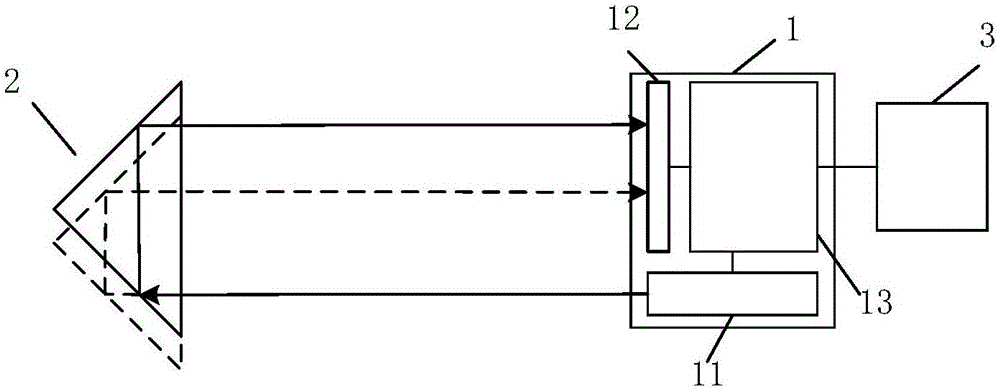
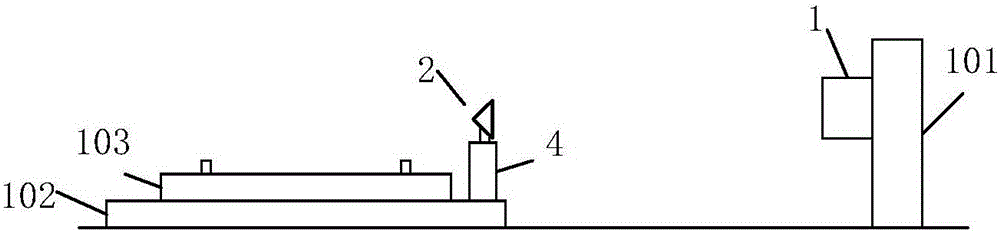
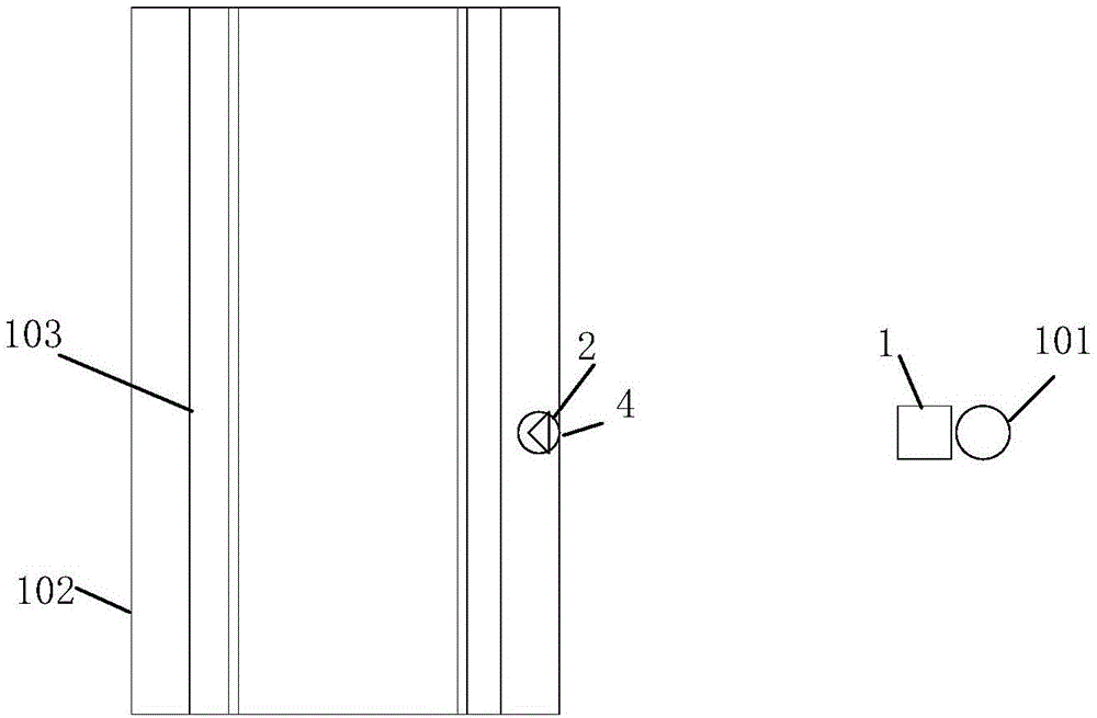
[0056] figure 2 A schematic diagram of an arrangement method of the present invention is shown. This arrangement method can be used to measure the vertical displacement of the line (caused by settlement or frost heaving, etc.), without being affected by longitudinal and lateral displacement. The displacement detection system is mainly composed of a photoelectric transmitting and receiving device 1 and a reflecting device 2 . The photoelectric transmitting and receiving device 1 is installed on the CPIII column 101, and the CPIII column is fixed on a deep foundation, so it can be considered that there will be no displacement, so it can be used as a measurement benchmark for line displacement. The reflection device 2 is installed on the line base plate 102 and the side of the track plate 103 through the column 4 . The reflection device 2 is displaced along with the line, so the displacement of the reflection device 2 is the line displacement. figure 1 A schematic diagram of ...

example 2

[0062] image 3 Another arrangement method of the present invention is shown, which can realize the longitudinal displacement measurement of line displacement. image 3 The middle reflection device 2 is a rectangular prism placed horizontally, and the laser and PSD in the photoelectric transmitting and receiving device are placed horizontally. The measurement principle is the same as that of Example 1. At the same time, this example can also be combined with Example 1, and the reflecting device can be changed into two right-angle prisms, one placed horizontally and the other vertically placed, and the photoelectric transmitting and receiving device is configured as two groups of lasers and PSD placed horizontally and vertically, which can be Realize simultaneous measurement of vertical and longitudinal displacement at the same measurement point.

example 3

[0064] Figure 4 It shows a schematic diagram of the arrangement of realizing the displacement monitoring of the subway tunnel by using the device of the present invention. A set of settlement detection devices can be used to realize the settlement detection of one measurement point. In order to realize the settlement monitoring of the entire interval, multiple sets of settlement detection devices can be used to transmit detection to each other. Such as Figure 4 As shown, the system installs a photoelectric transmitting and receiving device at the reference point of the platform, and installs a reflector and a photoelectric transmitting and receiving device at each measurement point in the interval, so that the photoelectric transmitting and receiving device at the previous point and the reflecting mirror at the next measuring point form a A set of settlement detection devices can monitor the relative displacement between two points. All the detection devices are connected ...


PUM


Abstract

The present invention provides a displacement detection system and a displacement detection method for railway equipment. The system comprises a photoelectric transmitter-receiver and at least one reflecting device. The photoelectric transmitter-receiver comprises a main control unit, a laser and a location-sensitive element. The reflecting device, the laser and the location-sensitive element are numerically equal and each reflecting device is arranged corresponding to one laser and one location-sensitive element. The laser is configured to emit the laser light to be irritated onto the corresponding reflecting device. The location-sensitive element is configured to receive the laser light reflected by the corresponding reflecting device. The main control unit is configured to control the light emission of the laser, receive a displacement signal sent from the location-sensitive element, process the displacement signal and generate a displacement detection result of the reflecting device relative to the photoelectric transmitter-receive. The reflecting device is composed of a rectangular prism and the bevel edge of the rectangular prism is arranged along the to-be-detected displacement direction. According to the technical scheme of the invention, the measurement process is simplified and the monitoring period is shortened. The real-time monitoring is realized and the error is reduced.

Description

technical field [0001] The invention belongs to the field of railway equipment safety, and in particular relates to line displacement monitoring, in particular to a displacement detection system and a displacement detection method for railway equipment. Background technique [0002] The operational safety of rail transit has high requirements on the service state of the line. The displacement of the line will pose a great threat to the safety of train operation. However, high-speed railway lines are affected by train operation and natural factors during operation, and are prone to displacement and deformation, such as subgrade settlement, line frost heaving in alpine regions, and track slab displacement. Since my country's high-speed railways mostly use ballastless tracks, when the line is deformed, it can only be adjusted through fasteners, and the adjustment range is very limited. When the displacement and deformation of the line are large, it will seriously endanger the...

Claims


Application Information

Patent Timeline
IPC IPC(8): G01B11/02
Inventor 王尧朱力强余祖俊
Owner BEIJING JIAOTONG UNIV
Why Eureka
Try Eureka