Novel tensile strength testing device for core sample

A technology of tensile strength and testing equipment, which is applied in the direction of measuring equipment, strength characteristics, and the use of stable tension/pressure to test the strength of materials, etc., can solve the problems of high cost, high time and labor costs, and inability to reuse, etc., to achieve Ease of operation and improved test efficiency

Active Publication Date: 2015-11-11
CHANGJIANG RIVER SCI RES INST CHANGJIANG WATER RESOURCES COMMISSION
View PDF5 Cites 6 Cited by
  • Summary
  • Abstract
  • Description
  • Claims
  • Application Information

AI Technical Summary

Problems solved by technology

[0003] 1. It is difficult to fully bond the pull plate and the core sample, and the pull plate is easy to fall off during the test. If it falls off, the epoxy cement needs to be removed and bonded again, which is time-consuming and laborious, and the success rate cannot be guaranteed;
[0004] 2. Epoxy resin has certain toxicity. The harmless treatment procedure of damaged test pieces and remaining materials is cumbersome and costly. If it is not handled properly, it will cause environmental pollution; and it will cause damage to the health of operators in the process of sample preparation and treatment of test pieces. ;
[0005] 3. Epoxy resin is expensive, and cannot be reused, and the test cost is high;
[0006] 4. After the epoxy resin has bonded the drawing plate and the core sample, it needs to stand still for 1 day before the loading test can be carried out. After the core sample is damaged, it will take a lot of time and manpower to peel off the core sample and the drawing plate, so one set of tests It usually takes 2 to 3 days for the equipment to complete the tensile strength test of a core sample, and it will take at least 1 week for a set of equipment to conduct a set of core sample tests, and the time and labor costs are high

Method used


Image

  • Novel tensile strength testing device for core sample
  • Novel tensile strength testing device for core sample
  • Novel tensile strength testing device for core sample

Examples


Embodiment Construction

[0029] The technical solutions in the present invention will be clearly and completely described below in conjunction with the accompanying drawings in the present invention.

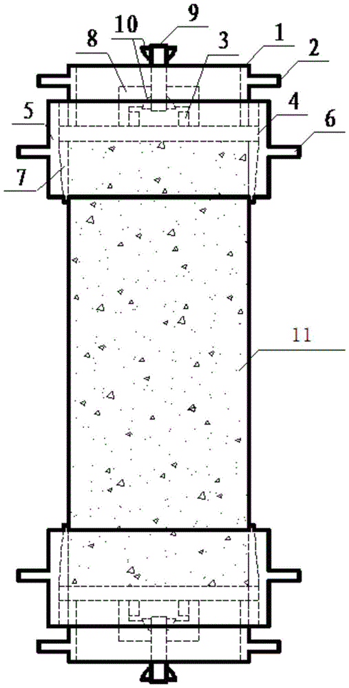
[0030] figure 1 Shown is the structure diagram of the novel core sample tensile strength testing device of the present invention, and the novel core sample tensile strength testing device includes a pull plate sleeve, a specimen fixing sleeve, a washer 7 and a pulling device.

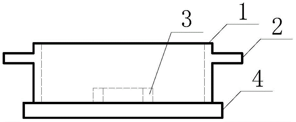
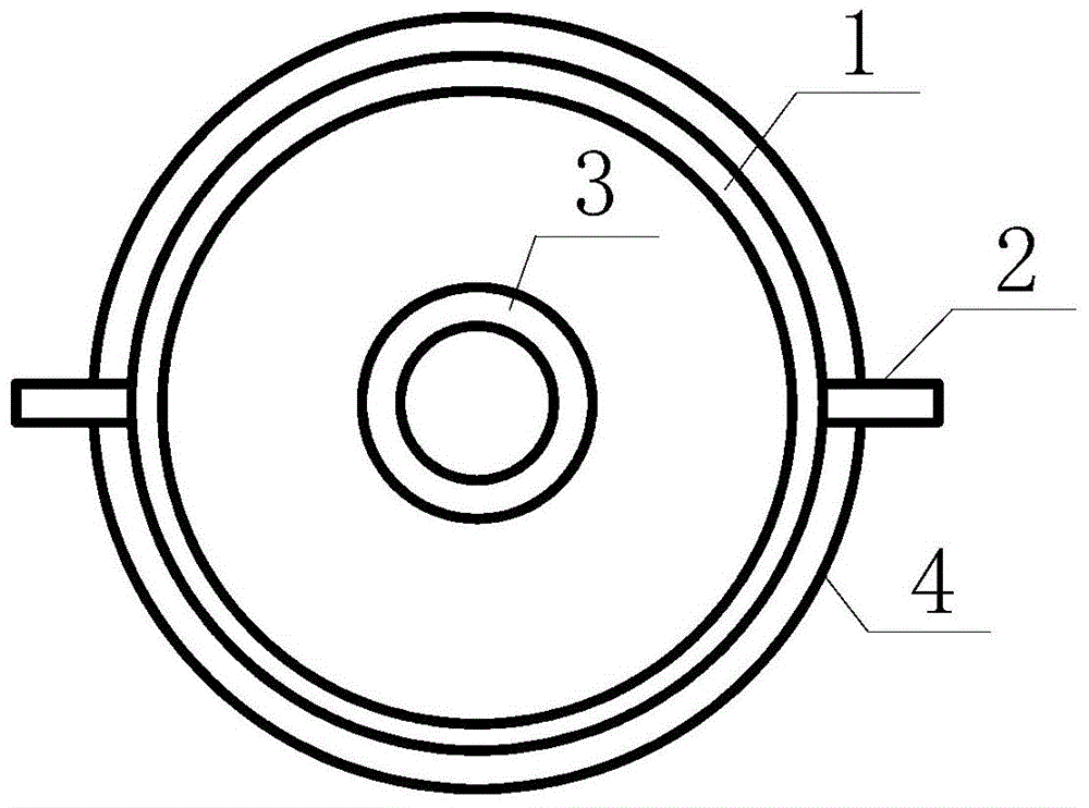
[0031] Please continue to refer to Fig. 2 (a) and Fig. 2 (b), the sleeve with the pull plate includes a steel ring 1, a handle 2 located on the outer wall of the steel ring 1, an outer wire pressing plate 4 connected to the bottom of the steel ring 1 and A small steel ring 3 with an outer wire located inside the steel ring 1 and connected to a pressing plate 4 with an outer wire. The outer wall of the steel ring 1 is provided with a handle 2 (handle 2 can be welded on the outer wall of the steel ring 1), the handle 2 is used to ...


PUM


Abstract

The invention provides a novel tensile strength testing device for a core sample. The novel tensile strength testing device comprises a sleeve with a pull board, a test piece fixing sleeve, a gasket and a pulling device, wherein the test piece fixing sleeve comprises a sleeve; the upper part of a sleeve wall of the sleeve is an inner thread part with uniform thickness; the inner thread part gradually becomes thick towards the lower side from the bottom and the section of the inner thread part is in a normal trapezoid shape; the gasket is composed of two semi-circular arc shapes with the same size, the thickness of the gasket is gradually reduced along the vertical direction and the section of the gasket is in a reversed trapezoid shape matched with the normal trapezoid shape of the lower part of the sleeve; the gasket sleeves the two ends of a test piece; after the test piece fixing sleeve sleeves the test piece, the two ends of the test piece are lifted so that the gasket and the test piece fixing sleeve can be mutually engaged to clamp the test piece; the sleeve with the pull board and the inner thread part of the sleeve are in thread connection; one end of the pulling device is hinged with the sleeve with the pull board; and the other end of the pulling device is hinged with a tension tester. With the adoption of the novel tensile strength testing device, preparation and treatment processes of sticking and pulling off the tensile test piece and the pull board, crushing the test piece, stripping off the pull board and the like are simplified, and the working efficiency is improved to the greatest extent.

Description

technical field [0001] The invention relates to a novel core sample tensile strength testing device. Background technique [0002] When the traditional method is used to test the tensile strength of concrete core samples, use building structural glue (usually epoxy resin) to bond the two ends of the core sample to the steel drawing plate respectively, and place it carefully for several hours (usually about 24 hours). load test. The traditional method mainly has the following disadvantages: [0003] 1. It is difficult to fully bond the pull plate and the core sample, and the pull plate is easy to fall off during the test. If it falls off, the epoxy cement needs to be removed and bonded again, which is time-consuming and laborious, and the success rate cannot be guaranteed; [0004] 2. Epoxy resin has certain toxicity. The harmless treatment procedure of damaged test pieces and remaining materials is cumbersome and costly. If it is not handled properly, it will cause environ...

Claims


Application Information

Patent Timeline
Patent Type & Authority Applications(China)
IPC IPC(8): G01N3/08G01N3/04
Inventor 杨华全李家正林育强董芸严建军彭尚仕李昊洁苏杰邝亚力杨梦卉石妍周世华颉志强肖开涛陈霞李响张亮王磊高志扬张建峰闫小虎杨华美陈群山胡小迎饶美娟
Owner CHANGJIANG RIVER SCI RES INST CHANGJIANG WATER RESOURCES COMMISSION
Why Eureka
Try Eureka