Inner isolation channel forced accelerated circulation transformer

A technology for accelerating circulation and transformers, applied in the direction of transformer/inductor cooling, etc., can solve the problems of affecting work efficiency, affecting heat dissipation, and increasing losses, and achieves the effects of improving heat dissipation efficiency, increasing convection speed, and increasing heat dissipation area

Active Publication Date: 2017-04-26
CHONGQING MINSHENG TRANSFORMER
View PDF5 Cites 0 Cited by
  • Summary
  • Abstract
  • Description
  • Claims
  • Application Information

AI Technical Summary

Problems solved by technology

Heat is generated during the working process of the transformer. Too high temperature will affect the efficiency of voltage conversion and increase the loss. Therefore, the design of the transformer attaches great importance to the heat dissipation performance. Existing transformers generally use heat dissipation pipes, and the heat dissipation pipes are divided into upper and lower parts. The terminals are respectively connected with the upper and lower parts of the inner space of the transformer oil tank to form a circulation loop. The entire circulation loop does not exceed the height of the transformer oil tank. The density of transformer oil at different temperatures is different. The oil temperature of the transformer oil in the entire circulation loop is layer by layer from top to bottom. In other words, the temperature of the upper layer is higher than that of the lower layer, and the distance between the existing transformer iron core winding and the upper cover of the transformer oil tank is relatively small, so that some iron core windings will still be immersed in the oil layer with a higher temperature, which will affect heat dissipation and influence Work efficiency, these are still to be solved by technology

Method used


Image

  • Inner isolation channel forced accelerated circulation transformer
  • Inner isolation channel forced accelerated circulation transformer

Examples


Embodiment Construction

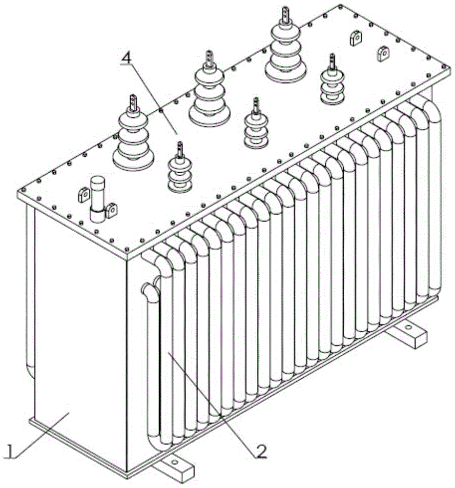
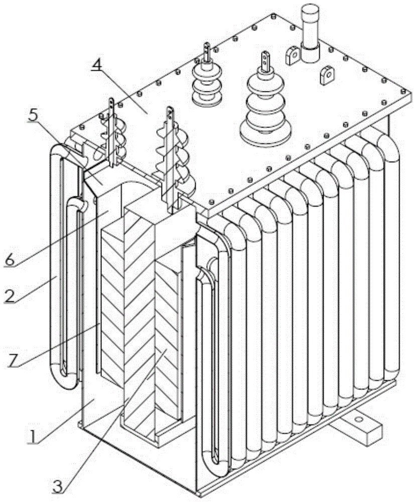
[0012] Embodiments of the present invention are as figure 1 , 2 As shown, the forced accelerated circulation transformer with internal isolation flow channel is provided with a transformer oil tank 1 and a heat dissipation pipe 2, and an iron core winding 3 is arranged in the transformer oil tank, and the distance between the upper part of the iron core winding and the upper cover 4 of the transformer oil tank is not less than the height of the transformer oil tank One quarter, the upper part retains a space for high-temperature oil, and the side wall of the transformer oil tank is provided with a transverse partition 5 extending inward. The coaming plate 6 with a distance from the bottom of the transformer oil tank, the upper edge of the coaming plate meets and connects with the inner edge of the transverse partition, the space between the coaming plate and the winding forms a flow channel 7, and the distance between the coaming plate and the winding is 0.5 cm to 1.5 cm, Bot...


PUM


Abstract

The invention discloses a forced accelerated circulation transformer with internal isolation channels. The forced accelerated circulation transformer comprises a transformer oil tank and cooling pipes, wherein an iron core winding is arranged in the transformer oil tank. The forced accelerated circulation transformer is characterized in that the distance between the upper part of the iron core winding and an upper cover of the transformer oil tank is less than one fourth of the height of the transformer oil tank, a transverse partition plate extending inwards is arranged on the side wall of the transformer oil tank, the connection position of the transverse partition plate and the side wall of the transformer oil tank is higher than the top of the iron core winding, an encircled plate of which the lower part is spaced apart from the bottom of the transformer oil tank encircles the winding, the upper-end edge of the encircled plate and the inner edge of the transverse partition plate are connected in a crossed way, channels are formed in the space between the encircled plate and the winding, the encircled plate and the transverse partition plate are both hot poor conductors, the two ports of each cooling pipe are respectively arranged above and below the transverse partition plate and are communicated with the interior of the transformer oil tank, and the cooling pipes are integrally in a G shape. By the forced accelerated circulation transformer, heat dissipation area is large, convective circulation speed is fast, the iron core winding is arranged at a low-temperature oil region, and thus, the transformer is ensured to work in a stable temperature environment.

Description

technical field [0001] The invention relates to an equipment transformer in the power industry, in particular to a forced accelerated circulation transformer with an inner isolation flow channel. Background technique [0002] my country has a vast territory and a dense power transmission network. Transformers are needed at the end of the network to convert voltage. Heat is generated during the working process of the transformer. Too high temperature will affect the efficiency of voltage conversion and increase the loss. Therefore, the design of the transformer attaches great importance to the heat dissipation performance. Existing transformers generally use heat dissipation pipes, and the heat dissipation pipes are divided into upper and lower parts. The terminals are respectively connected with the upper and lower parts of the inner space of the transformer oil tank to form a circulation loop. The entire circulation loop does not exceed the height of the transformer oil tan...

Claims


Application Information

Patent Timeline
Patent Type & Authority Patents(China)
IPC IPC(8): H01F27/08H01F27/14
Inventor 李金仁陈明德
Owner CHONGQING MINSHENG TRANSFORMER
Why Eureka
Try Eureka