
Shaft rotation limiting mechanism, shaft system and three-position electric switch using the mechanism

A technology of shaft rotation and limit mechanism, applied in the direction of air switch parts, etc., can solve the problems of increasing the pressure of the transmission connection mechanism, no mechanical limit device, affecting the service life of the shaft system, etc., and achieves high locking accuracy and failure points. Less, accurate and reliable operation

Active Publication Date: 2019-01-25
XJ ELECTRIC +2
View PDF3 Cites 1 Cited by
  • Summary
  • Abstract
  • Description
  • Claims
  • Application Information

AI Technical Summary

Problems solved by technology

[0004] In the existing electrical switches, limit switches that use electrical signals to work are generally installed, and there is no mechanical limit device. In this way, when the electrical signal fails or is delayed, it will appear when the driven shaft has rotated in place. The problem that the driving shaft will continue to rotate under certain circumstances will not only fail to achieve accurate positioning, but also fail to meet the design requirements of the operating mechanism. At the same time, it will also increase the pressure on the transmission connection mechanism in the shaft system formed by the driving shaft and the transmission shaft , affecting the service life of the shafting

Method used


Image

  • Shaft rotation limiting mechanism, shaft system and three-position electric switch using the mechanism
  • Shaft rotation limiting mechanism, shaft system and three-position electric switch using the mechanism
  • Shaft rotation limiting mechanism, shaft system and three-position electric switch using the mechanism

Examples


Embodiment Construction

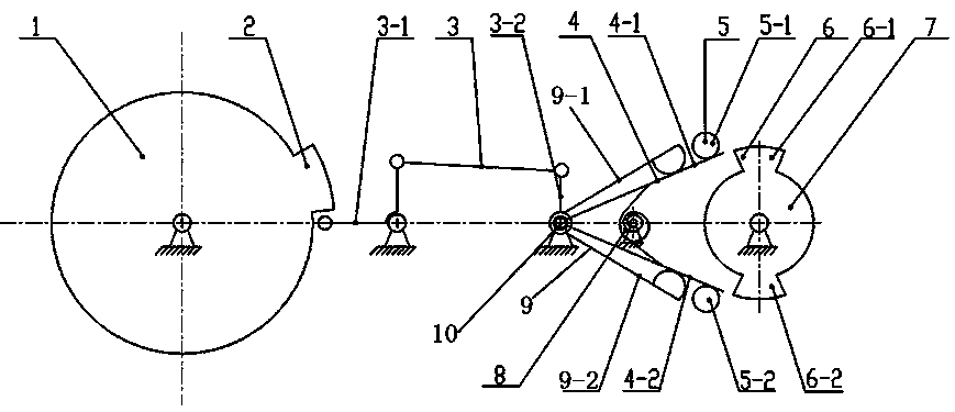
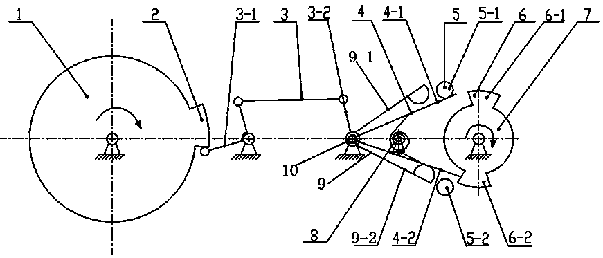
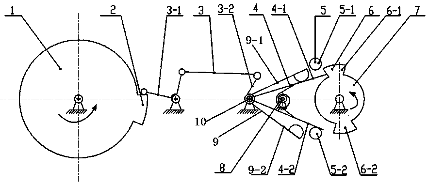
[0034] Such as Figure 1 to Figure 3 As shown, an embodiment of a shaft system using a shaft rotation limiting mechanism, the shaft system in this embodiment includes an input shaft 7 and an output shaft 1, and the input shaft 7 drives the output shaft 1 to rotate through a forward transmission mechanism, here The forward transmission mechanism is a commonly used transmission structure in the existing shaft system. The "forward" here refers to the transmission of the driving force from the input shaft 7 to the output shaft 1 in the transmission system.

[0035] The difference from the shaft system in the prior art is that in the shaft system provided in this embodiment, the output shaft 1 can limit the rotation of the input shaft 7 through the shaft rotation limiting mechanism of the reverse transmission. The rotation limiting mechanism includes a bracket, and the bracket is provided with a stop assembly 4, where the stop assembly 4 includes a clockwise stop bar 4-2 and an ant...


PUM


Abstract

The invention provides a rotation limiting mechanism for a rotating shaft, and a shaft system and a three-station electric switch employing the rotation limiting mechanism. The rotation limiting mechanism for the rotating shat comprises a bracket, wherein a clockwise stop lever and an anticlockwise stop lever are arranged on the bracket, and comprise stop positions and avoiding positions in reciprocating action strokes; the rotation limiting mechanism for the rotating shaft comprises a drive mechanism and reset elastic acting force; when drive acting force of the drive mechanism is greater than the reset elastic acting force, the corresponding stop lever moves to the corresponding stop position from the corresponding avoiding position under the action of the drive force of the drive mechanism; and when the reset elastic acting force is greater than the drive acting force of the drive mechanism, the corresponding stop lever moves to the corresponding avoiding position from the corresponding stop position under the action of the reset elastic acting force. Through coordination of the drive mechanism and the reset elastic acting force, switching of the clockwise stop lever and the anticlockwise stop lever between the stop positions and the avoiding positions is realized; through a mechanical drive mode, rotation limiting of a to-be-limited rotating shaft is effectively realized; and the operation is accurate and reliable.

Description

technical field [0001] The invention relates to a rotating shaft rotation limiting mechanism, a shaft system using the mechanism, and a three-position electric switch. Background technique [0002] In recent years, with the continuous advancement of high-voltage switchgear technology, pneumatic insulated metal-enclosed switches are developing in the direction of miniaturization, compounding, multi-functionalization of components, and intelligence. The isolating switch and the grounding switch are combined into a three-position switch, which saves Eliminate electrical operation interlocking, realize natural mechanical interlocking, there is no common misoperation between the isolating switch and the grounding switch, which requires the operating mechanism of the three-position switch not only to be able to realize the switching position, grounding position, The conversion between the three stations of the isolation position must also meet various mechanical and electrical int...

Claims


Application Information

Patent Timeline
Patent Type & Authority Patents(China)
IPC IPC(8): H01H31/08
CPCH01H31/08
Inventor 张杰李文峰张艳晓牛万宇王金雷赵玉芝张鹏李燕燕
Owner XJ ELECTRIC
Learn More