
A simple harmonic network parameter testing device and method

A harmonic network and parameter testing technology, applied in the direction of transmission monitoring, electrical components, transmission systems, etc., can solve the problems of difficult phase calibration, expensive comb generators, serious embargoes, etc., and achieve simple structure, good effect, phase calibration simple effect

Active Publication Date: 2017-10-03
CHINA ELECTRONIS TECH INSTR CO LTD
View PDF3 Cites 0 Cited by
  • Summary
  • Abstract
  • Description
  • Claims
  • Application Information

AI Technical Summary

Problems solved by technology

[0004] (1) Comb generators with a wide frequency band (such as 10M~26.5 / 40 / 50GHz) are very expensive, and the foreign embargo is serious
[0005] (2) The numerical interpolation of the phase and the phase calibration of the comb generator are very difficult

Method used


Image

  • A simple harmonic network parameter testing device and method
  • A simple harmonic network parameter testing device and method
  • A simple harmonic network parameter testing device and method

Examples


Embodiment 1

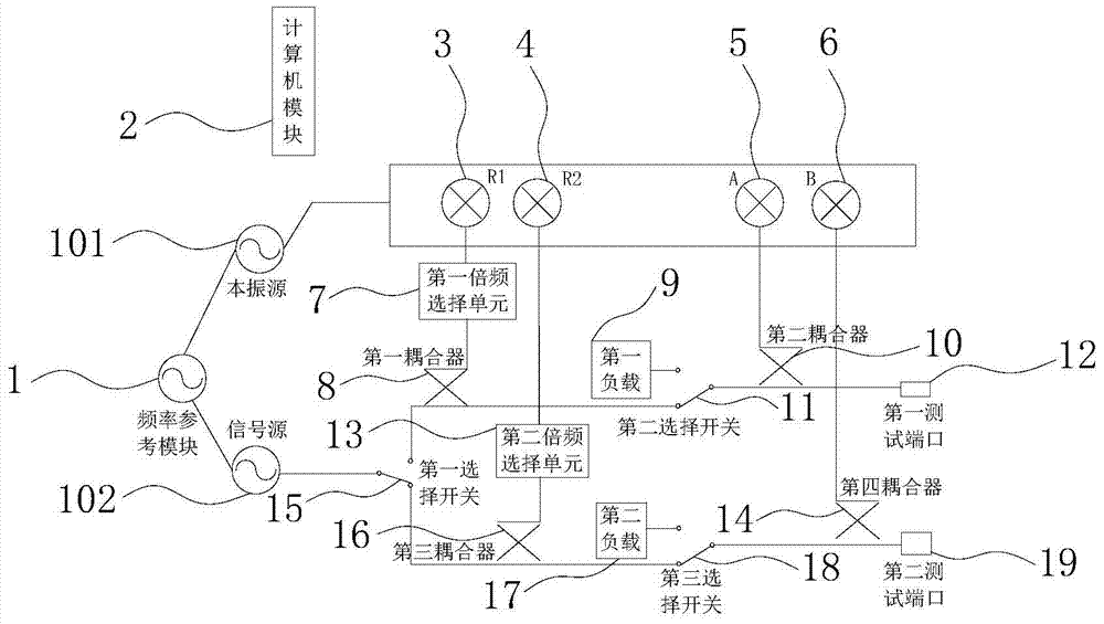
[0046] Such as figure 1 As shown, a hardware schematic diagram of a simple harmonic network parameter testing device, including a frequency reference module 1, a selection switch, a test port, a coupler, a frequency multiplication selection unit, a down-conversion receiver, a computer module 2 and a load;

[0047] The selection switch includes a first selection switch 15, a second selection switch 11 and a third selection switch 18;

[0048] The test port includes a first test port 12 and a second test port 19;

[0049] The frequency multiplication selection unit includes a first frequency multiplication selection unit 7 and a second frequency multiplication selection unit 13 for providing a phase reference;

[0050] The down-conversion receiver includes the R1 receiver 3 for detecting the outgoing wave of the first test port 12, the R2 receiver 4 for detecting the outgoing wave of the second test port 19, and the R2 receiver 4 for detecting the outgoing wave of the first tes...

Embodiment 2

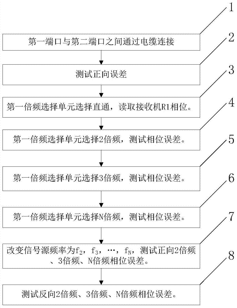
[0060] On the basis of the above-mentioned embodiments, the present invention provides a simple harmonic network parameter testing method, which must be calibrated before the test. Firstly, the down-conversion receiver is calibrated. The calibration method is to use a power meter to test the actual output The interpolation of the received power of the machine is performed to compensate for the phenomenon; secondly, the error of load matching, source matching, and isolation under the basic conditions is calibrated, and the open circuit, short circuit, load, and through are calibrated using the SOLT method. Also need to carry out the phase calibration of frequency multiplication selection unit, be used to provide phase reference, the phase calibration method of frequency multiplication selection unit (such as figure 2 shown), wherein, proceed as follows:

[0061] Step 1: connecting the first test port and the second test port through a cable;

[0062] Step 2: The first selecti...


PUM


Abstract

The invention discloses a simple harmonic network parameter testing device and method, belonging to the field of harmonic network parameter testing, including a frequency reference module, a selection switch, a test port, a coupler, a frequency multiplication selection unit, a down-conversion receiver, and a computer Module and load; use the above device to first perform phase calibration of the multiplier selection unit, and then perform harmonic network parameter testing. A simple harmonic network parameter testing device and method of the present invention has reasonable design, simple structure, and low cost. The frequency multiplication selection unit is used to realize the selection of signal direct-through, double frequency, triple frequency to N-multiple frequency, and frequency multiplication The excitation of the selection unit uses the input signal instead of the frequency reference signal, no interpolation algorithm is required, and the phase calibration is simple, which effectively solves the high cost of existing harmonic network parameter testing, cumbersome calibration and testing processes, and the need to introduce numerical interpolation algorithms and comb generators The phase calibration is very difficult and has good promotion value.

Description

technical field [0001] The invention belongs to the field of harmonic network parameter testing, and in particular relates to a simple harmonic network parameter testing device and method. Background technique [0002] With the continuous development of modern microwave and millimeter wave communication systems, high-speed broadband technology has become a development trend. This new technology often requires communication systems to have the characteristics of multi-carrier and large dynamic range, so the linearity requirements for microwave devices are very strict. . Therefore, for a microwave component, such as a wide bandgap semiconductor, nonlinear testing methods have become the focus of microwave design and testing industries. The current nonlinear test of microwave components is based on the harmonic model, that is, the network input selects a single-tone signal (it can be a point frequency or a sweep frequency), and the acceptance frequency of the network under tes...

Claims


Application Information

Patent Timeline
Patent Type & Authority Patents(China)
IPC IPC(8): H04B17/309
Inventor 杨保国梁胜利李树彪曹志英王尊峰黎明敏张庆龙许春卿
Owner CHINA ELECTRONIS TECH INSTR CO LTD
Learn More