Rebar head portion upsetting machine and use method thereof

An upsetting machine and upsetting technology, applied in the field of cold upsetting machines, can solve problems such as inaccurate positioning, achieve stable performance of the whole machine, improve stability and accuracy, and improve stability

Pending Publication Date: 2015-11-18
MAANSHAN CITY ZHIFENG MACHINERY
View PDF10 Cites 3 Cited by
  • Summary
  • Abstract
  • Description
  • Claims
  • Application Information

AI Technical Summary

Problems solved by technology

[0005] Aiming at the inaccurate positioning of the existing upsetting machine and the problem of steel bar sliding during upsetting, the present invention provides a steel bar head upsetting machine and its use method

Method used


Image

  • Rebar head portion upsetting machine and use method thereof
  • Rebar head portion upsetting machine and use method thereof

Examples


Embodiment 1

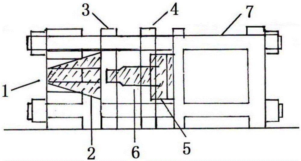
[0042] An upsetting machine for the head of a steel bar, an upsetting die, an upsetting device, and a guide rod 7 are installed on the frame, and the upsetting die and the upsetting device are arranged on the frame through the guide rod 7 in sequence from left to right, The frame is used to fix the upsetting die and upsetting device. When the upsetting device squeezes the steel bars in the upsetting die, the guide rod 7 plays the role of positioning guide. The upsetting die in the prior art does not have the positioning guide of the guide rod 7. After long-term operation, the upsetting die and the upsetting Dislocation of the device, the present invention utilizes the positioning and guiding function of the guide rod 7 to ensure that the end face of the steel bar in the upsetting mold and the upsetting head 6 on the upsetting device will not be dislocated, and improve the stability and accuracy of the impact of the upsetting head 6 , thereby improving the service life of the u...

Embodiment 2

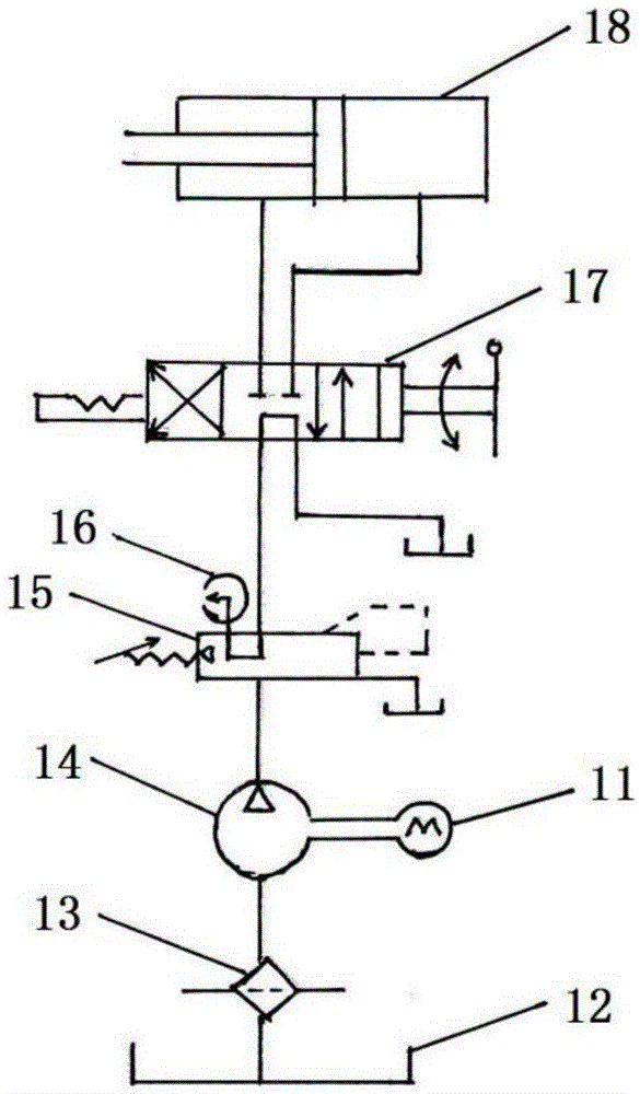
[0057] The structure and use method of this embodiment are the same as those of Embodiment 1, wherein the working stroke of the piston rod is 60mm, the maximum stroke is 152mm, the rated upsetting force is 1880kN, the maximum upsetting force is 2820kN, and the motor power is 4kW, which is different from the conventional super Compared with the motor power of the high-pressure pump, no additional cooling system is required, and the flow rate of the high-pressure oil pump 14 is 5.6L / min, which improves work efficiency and reduces costs. When the conventional upsetting machine works, one piece of equipment can generally process one hundred steel bars per shift. To speed up the progress can only be realized by increasing the number of equipment, which consumes a lot of manpower and material resources. The steel bar of the present invention can process three hundred steel bars, which improves the work efficiency. Efficiency, saving manpower and material resources. Its operation ste...


PUM


Abstract

The invention discloses a rebar head portion upsetting machine and a use method thereof and belongs to the field of cold headers. An upsetting die and an upsetting device are installed on a machine frame. The rebar head portion upsetting machine comprises guide rods; the guide rods penetrate through the upsetting die and the upsetting device sequentially be arranged on the machine frame from left to right; the upsetting die comprises a clamping die and a die cavity; the die cavity is located in the clamping die; the upsetting device comprises an upset head cap and an upsetting head; the upsetting head is arranged at the left end of the upset head cap; the right end of the upset head cap is arranged on a hydraulic control system. The upsetting machine further comprises a front movable board and a rear movable board, wherein the front movable board is arranged on the right side of the upsetting die; the upsetting head on the upsetting device sequentially penetrates through the rear movable board and the front movable board; the left end of the rear movable board is arranged on the upset head cap; the guide rods penetrate through the front movable board and the rear movable board and the front movable board and the rear movable board are connected through a lead screw; the guide rods are cylindrical; the rear movable board can move on the guide rods left and right. The rebar head portion upsetting machine is large in upsetting force, high in upsetting quality and stable in complete-machine performance.

Description

technical field [0001] The invention relates to the field of cold heading machines, in particular to a steel bar head heading machine and a method for using the same. Background technique [0002] The steel bar upsetting machine is used in the straight thread mechanical connection technology of building steel bars, in order to keep the effective bottom diameter cross-sectional area of ​​the thread not less than the basic cross-sectional area of ​​the steel bar base material, so as to perform cold heading on the steel bar head before cutting the thread. , Special mechanical equipment for diameter increase processing. The steel bar upsetting machine is to upset both ends of the steel bar for construction and then process the thread, and connect it with a threaded sleeve when in use, which can increase the strength of the connection part. This is the application practice of large-scale construction steel bars in the world. The conventional upsetting method is to use an ultra-h...

Claims


Application Information

Patent Timeline
Patent Type & Authority Applications(China)
IPC IPC(8): B21F5/00
Inventor 王广流
Owner MAANSHAN CITY ZHIFENG MACHINERY
Why Eureka
Try Eureka