
Making device and method for soft glass optical fiber preform

A technology for optical fiber preforms and manufacturing devices, which is applied in glass manufacturing equipment, manufacturing tools, etc. It can solve the problems of difficult to obtain core layer preforms, difficult timing and lifting height, and difficult to produce glass rods with excellent optical uniformity. and other problems, to avoid surface devitrification effect, ensure optical uniformity, and achieve the effect of excellent optical uniformity

Active Publication Date: 2015-11-18
SHANGHAI INST OF OPTICS & FINE MECHANICS CHINESE ACAD OF SCI
View PDF5 Cites 13 Cited by
  • Summary
  • Abstract
  • Description
  • Claims
  • Application Information

AI Technical Summary

Problems solved by technology

However, the disadvantage of this method is also very obvious
First of all, it is difficult to accurately grasp the timing and lifting height of the mold, which is difficult, poor in stability and consistency; secondly, the core material for suction injection often presents a tapered shape, and it is difficult to obtain a preform with a constant core diameter; The pouring method adopted by the method determines that it is difficult to produce high-quality glass rods with excellent optical uniformity
[0007] To sum up, there is currently no suitable preform production equipment and technology that can produce soft glass optical fiber preforms with closed core-cladding interface, constant longitudinal dimension, and good optical uniformity.

Method used


Image

  • Making device and method for soft glass optical fiber preform
  • Making device and method for soft glass optical fiber preform
  • Making device and method for soft glass optical fiber preform

Examples


Embodiment Construction

[0039] The present invention will be further described below in conjunction with the accompanying drawings, but the protection scope of the present invention should not be limited thereby.

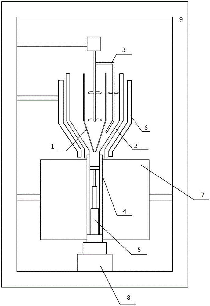
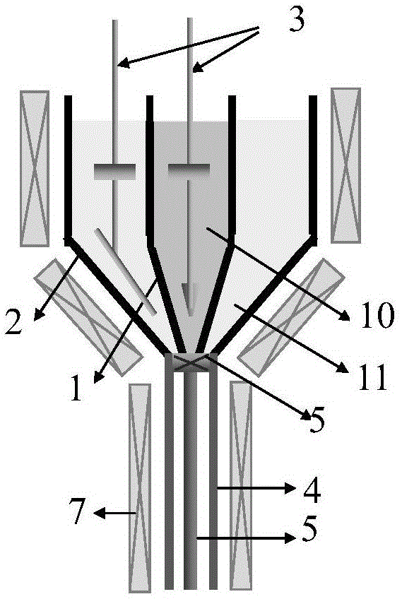
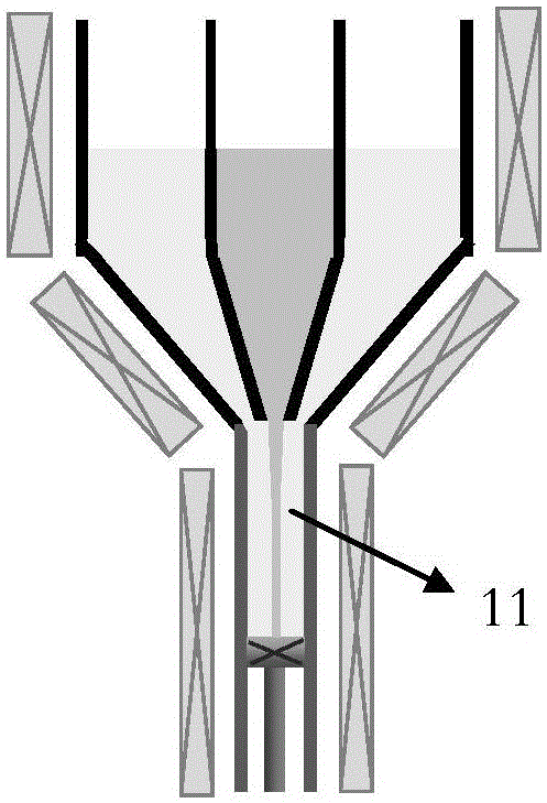
[0040] Such as Figure 1-2As shown, a soft glass optical fiber preform manufacturing device based on double-crucible laminar flow leak injection includes a coaxial inner crucible 1 and an outer crucible 2, and the outer crucible is longer than the inner crucible so as to be able to seal the After the inner crucible is completely surrounded, a stirring device 3 is respectively arranged in the inner crucible 1 and the outer crucible 2, and the lower part of the inner crucible 1 has an outlet communicating with the mold 4, and the mold 4 has a built-in piston and its electric drive mechanism 5, the inner crucible 1 and the outer crucible 2 are placed in the high-temperature furnace 6, the mold 4 is placed in the heating element 7, and the mold 4 and the electric drive mechanism 5 are placed o...


PUM


Abstract

The invention relates to a double crucible laminar leakage pouring based making device and method for a soft glass optical fiber perform. The device comprises an inner crucible and an outer crucible that are coaxial. The outer crucible is longer than the inner crucible so as to be able to completely surround the inner crucible after melting sealing. The inner crucible and the outer crucible are internally provided with a stirring apparatus respectively. The lower part of the inner crucible has an outlet communicated with a die, and the die is internally equipped with a piston and an electric driving mechanism thereof. The inner crucible and the outer crucible are placed in a high temperature furnace, the die is placed in a heating element, and the die and the electric driving mechanism are placed on a lifting platform. The inner crucible, the outer crucible, the stirring apparatus, the high temperature furnace, the heating element and the lifting platform are installed on a tower frame respectively. According to the invention, the descending speed of the piston determines the leakage pouring rate, and by controlling the viscosity and leakage pouring rate of molten glass, the Reynolds number of the leakage pouring process can be controlled, thus ensuring a laminar leakage pouring process.

Description

technical field [0001] The invention relates to a soft glass optical fiber, also known as a multi-component glass optical fiber manufacturing technology, in particular to a soft glass optical fiber preform manufacturing device and method based on double-crucible laminar flow leakage injection. Background technique [0002] Soft glass fiber refers to non-quartz-based multi-component glass fiber, which has some unique optical and spectroscopic properties. For example, high solubility of rare earth particles, wide gain spectrum, high nonlinearity, etc. It can be widely used in single-frequency lasers, ultrashort pulse lasers and Raman lasers. Some soft glass fibers are transparent in the mid-infrared and can be widely used in fiber laser devices in the mid-infrared band. This is an important application that silica fiber cannot replace at all. Mid-infrared laser sources have important applications in the fields of national defense, biomedicine, and cutting-edge scientific re...

Claims


Application Information

Patent Timeline
IPC IPC(8): C03B37/012
Inventor 廖梅松李夏薛天峰高松
Owner SHANGHAI INST OF OPTICS & FINE MECHANICS CHINESE ACAD OF SCI
Learn More