Artificial plastic hinge at beam end of building concrete structure and construction method thereof

A technology of concrete structure and plastic hinge, which is applied in the direction of building structure and architecture, and can solve the problems that have not been widely used

Inactive Publication Date: 2015-11-18
CHANGAN UNIV
View PDF5 Cites 4 Cited by
  • Summary
  • Abstract
  • Description
  • Claims
  • Application Information

AI Technical Summary

Problems solved by technology

Although these methods have achieved the seismic failure mode of the beam-hinge mecha

Method used


Image

  • Artificial plastic hinge at beam end of building concrete structure and construction method thereof
  • Artificial plastic hinge at beam end of building concrete structure and construction method thereof
  • Artificial plastic hinge at beam end of building concrete structure and construction method thereof

Examples


Embodiment 1

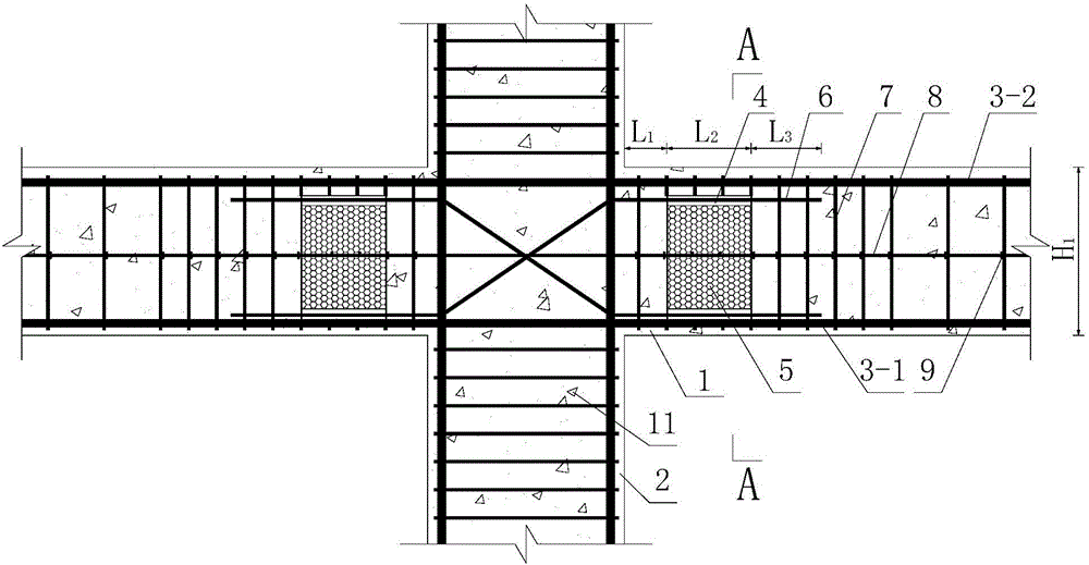
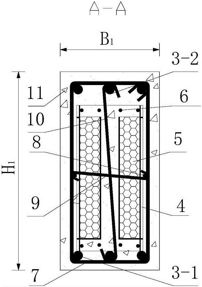
[0148] like figure 1 as well as Figure 3 ~ Figure 7 As shown, the artificial plastic hinge at the beam end of the building concrete structure of the present invention, the building concrete structure includes a beam 1 to be set and a column connected to the beam 1 to be set, and the beam 1 to be set is provided with a beam bottom longitudinal reinforcement 3- 1. Beam top longitudinal reinforcement 3-2, beam stirrup 7, beam waist reinforcement 8 and S-shaped stirrup 10, the artificial plastic hinge at the beam end includes a plastic hinge structure arranged at the end of the beam 1 to be installed and the column connected box 4, and the plastic hinge structural reinforcement 6 and tie reinforcement 9 for fixing the plastic hinge structural box 4; the plastic hinge structural box 4 is placed between the longitudinal reinforcement 3-1 at the bottom of the beam and the longitudinal reinforcement 3-2 at the top of the beam, so The number of the plastic hinge structural steel bars...

Embodiment 2

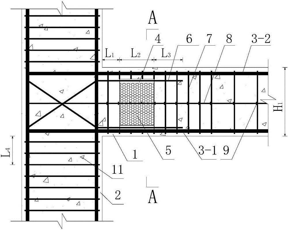
[0157] like figure 2 as well as Figure 3 ~ Figure 7 As shown, the difference between this embodiment and Embodiment 1 is that the column is a side column 2-2, the number of the plastic hinge construction box 4 is one, and one end of the plastic hinge construction steel bar 6 crossed in pairs Through the plastic hinge structure reinforcement hole 12 arranged on the plastic hinge structure box 4, the other end of the plastic hinge structure reinforcement 6 crossed in pairs stretches out from the connection node between the beam 1 to be set and the column and connects with the side column 2-2 rebar connections. All the other structures are the same as in Example 1.

[0158] During specific implementation, the plastic hinge structural reinforcement 6 extends out the length L of the beam 1 to be set. 4 is 250mm.

[0159] like Figure 8 As shown, the method for constructing the artificial plastic hinge at the beam end of the building concrete structure in embodiment 1 and emb...


PUM

PropertyMeasurementUnit
Wall thicknessaaaaaaaaaa
Diameteraaaaaaaaaa
Lengthaaaaaaaaaa

Abstract

The invention discloses an artificial plastic hinge at the beam end of a building concrete structure. The artificial plastic hinge comprises a plastic hinge construction box, plastic hinge construction steel bars and pulling steel bars. The plastic hinge construction box is arranged between a beam-bottom longitudinal steel bar and a beam-top longitudinal steel bar. The multiple plastic hinge construction steel bars are pairwise intersected to be arranged at the connecting joint of a to-be-arranged beam and a to-be-arranged column. Plastic hinge construction steel bar holes are formed in the portions, close to the upper edge and the lower edge, of the front face of the plastic hinge construction box. Two flame-retardant-foam-board containing cavities formed side by side and used for containing flame retardant foam boards are formed inside the plastic hinge construction box. S-shaped stirrups are arranged between the two flame-retardant-foam-board containing cavities, and the portion between the two flame-retardant-foam-board containing cavities is poured with concrete. Pulling steel bar holes are formed in the middles of the lateral sides of the plastic hinge construction box. The invention further discloses a construction method for the artificial plastic hinge at the beam end of the building concrete structure. By means of the artificial plastic hinge and the construction method, design is reasonable, the good seismic capacity of the structure can be guaranteed, the construction process is simplified, the construction quality is guaranteed, practicability is high, and use and popularization are convenient.

Description

technical field [0001] The invention belongs to the technical field of civil engineering design and construction, and in particular relates to an artificial plastic hinge at the beam end of a building concrete structure and a construction method thereof. Background technique [0002] Reinforced concrete structure is one of the most widely used building structures in my country and even in the world. "Strong columns and weak beams" and "strong joints and weak members" are the basic design requirements for structures in various countries' seismic codes. However, due to the over-reinforcement in the design, the floor slab connected to the beam, the filling wall above the beam, and the construction quality, on the one hand, the actual stiffness of the beam is artificially increased, and on the other hand, the bearing capacity of the beam-column joint is artificially reduced. Rigidity makes it difficult for the actual building structure to achieve the above design purposes under...

Claims


Application Information

Patent Timeline
IPC IPC(8): E04B1/36E04B1/58
Inventor 黄华吴涛刘伯权刘喜
Owner CHANGAN UNIV
Why Eureka
Try Eureka