A device and method for reducing shrinkage difference of concrete foundation

A concrete foundation and concrete layer technology, which is applied in the processing of building materials, construction, building structure, etc., can solve the problems of small contact area between resistance wire and concrete, increasing the risk of cracking of newly poured concrete, and high local temperature of the resistance wire. Achieve the effect of low realization difficulty, solving practical problems of quality control, and small transformation workload

Active Publication Date: 2017-08-25
CCCC WUHAN HARBOR ENG DESIGN & RES
View PDF6 Cites 0 Cited by
  • Summary
  • Abstract
  • Description
  • Claims
  • Application Information

AI Technical Summary

Problems solved by technology

However, in actual engineering, since most of the reinforced concrete structures are large in size, after multiple processes such as binding steel bars, cleaning formwork, and installing embedded parts, the interval between layers of pouring is often greater than 15 days or even several months, which greatly increases Risk of Cracking in Freshly Poured Concrete
[0003] At present, there is a technology that uses pre-embedded thermal resistance wires to increase the temperature of old concrete and reduce the shrinkage difference. However, an electric heating system and wires are added to the pre-embedded resistance wires, which interferes with concrete pouring, and electric heating is prone to excessive local temperature of the resistance wires. The problem is that the contact area between the resistance wire and the concrete is small, and the heat transfer efficiency is not good

Method used


Image

  • A device and method for reducing shrinkage difference of concrete foundation

Examples


Embodiment 1

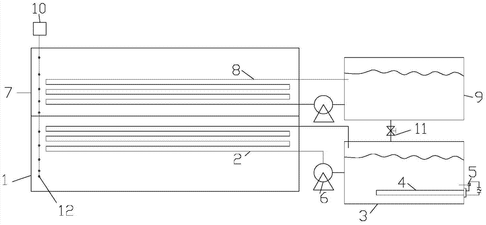
[0034] like figure 1 As shown, the embodiment of the present invention provides a device for reducing the shrinkage difference of the concrete foundation, including a first cooling water pipe 2 and a second cooling water pipe 8, both of which are serpentine pipes. Wherein, the first cooling water pipe 2 and the second cooling water pipe 8 are existing cooling water pipe systems in the prior art, which reduces the difficulty and cost of system implementation.

[0035] The first cooling water pipe 2 is connected with the hot water circulating water tank 3, the second cooling water pipe 8 is connected with the cold water circulating water tank 9, the first cooling water pipe 2 and the second cooling water pipe 8 are connected with the hot water circulating water tank 3 and the cold water circulation through the circulating water pump 6 respectively Water tank 9 is connected. The hot water circulating water tank 3 is communicated with the cold water circulating water tank 9 throu...

Embodiment 2

[0040] Embodiments of the present invention provide a method for reducing the shrinkage difference of concrete foundations, comprising the following steps:

[0041] S1. Concrete the lower concrete layer 1, pre-embed the first cooling water pipe 2 in the horizontal direction at the pouring front of the lower concrete layer 1, the number of the first cooling water pipe 2 is at least one, and the first cooling water pipes 2 are stacked on top of each other In the area between the surface of the lower concrete layer 1 and a certain depth, the certain depth is 0.2 times the transverse width of the concrete. It should be noted that this area is a strong confinement area. Then the temperature measuring element 12 is pre-embedded around the first cooling water pipe 2, and the temperature measuring element 12 is respectively arranged in the middle part of the vertical direction of the lower concrete layer 1, and the temperature measuring element 12 is used to monitor the internal maximu...


PUM


Abstract

The invention relates to a device for reducing shrinkage difference of concrete foundation. The hot water circulating water tank and the cold water circulating water tank are connected through a valve; the hot water circulating water tank is provided with an electric heating tube, and the electric heating tube passes through the side wall of the hot water circulating water tank and is connected with a temperature control switch ; It also includes a temperature acquisition system, the temperature acquisition system includes a control system and a temperature measuring element electrically connected to the control system, and the control system is electrically connected to the temperature control switch. The invention also provides a method for reducing the shrinkage difference of the concrete foundation. The first cooling water pipe is used to conduct hot water in reverse to raise the temperature of the lower concrete layer poured first, so as to reduce the upper concrete layer poured later and the lower concrete layer poured earlier. The purpose of the temperature difference of the base layer is to make the temperature deformation of the upper concrete layer poured later and the lower concrete layer poured earlier tend to be synchronized, and reduce the degree of constraint of the upper concrete layer poured later, so as to solve the problem of high temperature stress level and the upper layer poured later The problem of high risk of concrete layer cracking.

Description

technical field [0001] The invention relates to the technical field of civil engineering, in particular to a device and a method for reducing shrinkage difference of concrete foundations. Background technique [0002] In order to reduce the temperature stress of mass concrete and reduce the risk of cracking of newly poured concrete, layered pouring measures are often adopted. This method is suitable for mass concrete construction. Generally, the pouring interval between layers is required to be controlled within 7 to 10 days to avoid new and old concrete. The shrinkage difference between the concrete is too large, and mutual restraint causes the newly poured concrete to crack. However, in actual projects, since most of them are reinforced concrete structures with large sizes, after multiple processes such as binding steel bars, cleaning formwork, and installing embedded parts, the interval between layers of pouring is often greater than 15 days or even several months, which ...

Claims


Application Information

Patent Timeline
Patent Type & Authority Patents(China)
IPC IPC(8): E04G21/02
Inventor 刘可心屠柳青焦运攀李进辉秦明强李顺凯吴柯
Owner CCCC WUHAN HARBOR ENG DESIGN & RES
Why Eureka
Try Eureka