
U-shaped-row-tube type fused salt steam generating device and method

A steam generating device and tube-and-tube technology, which is applied in the field of U-shaped tube-and-tube molten salt steam generating device, can solve the problems of large flow resistance and backflow resistance, difficult control of water vapor parameters, complicated structure of heat-absorbing sleeve, etc. Achieve the effect of less heat loss, easy disassembly and dredging, and easy promotion

Inactive Publication Date: 2015-11-18
SUN YAT SEN UNIV
View PDF9 Cites 6 Cited by
  • Summary
  • Abstract
  • Description
  • Claims
  • Application Information

AI Technical Summary

Problems solved by technology

In the solar molten salt casing type steam generating device, the high temperature resistant selective coating on the outer wall of the casing is used to absorb solar radiation energy, and transfer the absorbed heat to the molten salt in the molten salt casing, and further to the water in the serpentine inner pipe to form steam, but the device has the disadvantages that the water vapor parameters are not easy to control, the heat-absorbing sleeve has a complex structure, and the processing is difficult.
The molten salt shell-and-tube steam generating device includes a shell-and-tube heat exchanger, a steam separation output component and a heating and heat preservation component. The heating and heat preservation component can prevent the molten salt from solidifying. The molten salt flowing through the shell has a large effective heat storage capacity and stable parameters. Advantages, but it has the problem that the molten salt at the bottom of the shell is not easy to flow back
Molten salt coil steam generating device, including water tank system, coil system, and steam output system, has the advantages of good steam generation stability and strong controllability, but the flow path of molten salt in the coil is long, and the flow resistance and backflow Relatively large resistance

Method used


Image

  • U-shaped-row-tube type fused salt steam generating device and method

Examples


Embodiment Construction

[0027] The present invention will be further described in detail below in conjunction with examples and accompanying drawings, but the embodiments of the present invention are not limited thereto.

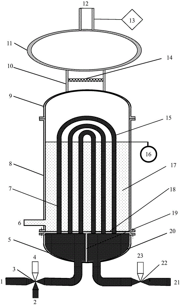
[0028] In this embodiment, a U-shaped tubular molten salt steam generating device has a structure such as figure 1 As shown, it includes U-shaped tube heat exchange system, steam output system, and molten salt input and output system; the steam output system is set on the top of the U-shaped tube heat exchange system, and the molten salt input and output system is set on the U-shaped tube heat exchange system bottom. In this embodiment, the molten salt input and output system can not only input and output molten salt for heating, but also input and output high-temperature gas for preheating by setting the inlet four-way valve 3 and the outlet three-way valve 22 .

[0029] In this embodiment, the U-shaped tube heat exchange system mainly includes a top connecting head 9, a tube bod...


PUM


Abstract

The invention provides a U-shaped-row-tube type fused salt steam generating device and method. The U-shaped-row-tube type fused salt steam generating device comprises a U-shaped-row-tube heat exchange system, a steam output system and a fused salt input-output system. The steam output system is arranged at the top of the U-shaped-row-tube heat exchange system. The fused salt input-output system is arranged at the bottom of the U-shaped-row-tube heat exchange system. Circulating of high temperature gas and circulating of fused salt can be further controlled through an inlet four-way valve and an outlet three-way valve at the same time. The height of the liquid level and the steam generating speed can be adjusted through a liquid level controller. The parameters of output steam are kept stable through a steam parameter measuring and control device. The U-shaped-row-tube type fused salt steam generating method includes the steps that a system is preheated through the high temperature gas, then fused salt pouring, steam generating and steam outputting are sequentially carried out, and finally fused salt backflow and U-shaped row tube cleaning are carried out. According to the U-shaped-row-tube type fused salt steam generating device and method, the steam yield is large, the parameters are controllable, backflow of the fused salt is easy, blocking is not prone to occurrence, the heat efficiency of the system is high, the structure is simple, the service life is long, and the requirements of the solar high-temperature heat utilization technical field, the solar waste-heat utilization technical field and the nuclear electric power generation technical field can be well met.

Description

technical field [0001] The invention relates to the technical field of solar medium-high temperature heat utilization, waste heat utilization and nuclear power generation, and in particular to a U-shaped tubular molten salt steam generating device and method. Background technique [0002] Energy shortage and environmental problems of fossil fuels have become major bottlenecks restricting global economic and social development. In recent years, my country has become the world's largest oil consumer and the second largest crude oil importer, and the situation of energy conservation and emission reduction is becoming increasingly severe. In order to solve energy shortage and environmental problems, on the basis of vigorously developing fossil fuels, nuclear energy and hydropower, it is necessary to improve energy utilization efficiency and vigorously develop renewable energy. Industry is the field with the greatest energy-saving potential. At present, the energy utilization ef...

Claims


Application Information

Patent Timeline
Patent Type & Authority Applications(China)
IPC IPC(8): F22B1/06
Inventor 陆建峰丁静袁溢博杨建平王维龙
Owner SUN YAT SEN UNIV
Learn More