Online testing device for safety valve and online testing method thereof

A detection device and safety valve technology, applied in the direction of measuring devices, testing of mechanical components, testing of machine/structural components, etc., can solve problems such as poor safety and complicated operation, and achieve improved applicability, good safety, and intelligent devices effect

Inactive Publication Date: 2015-11-18
李治涛
View PDF6 Cites 20 Cited by
  • Summary
  • Abstract
  • Description
  • Claims
  • Application Information

AI Technical Summary

Problems solved by technology

[0008] In order to overcome the disadvantages of poor safety and complicated operation in the existing safety valve on-line detection device, the object of the present invention is to provide a safety valve on-line detection device, a safety valve judgment method and an on-line detection method, the device and The judgment method and online detection method can improve the applicability of the safety valve, enhance the safety of the safety valve calibration work, and eliminate potential safety hazards

Method used


Image

  • Online testing device for safety valve and online testing method thereof
  • Online testing device for safety valve and online testing method thereof
  • Online testing device for safety valve and online testing method thereof

Examples


Embodiment 2

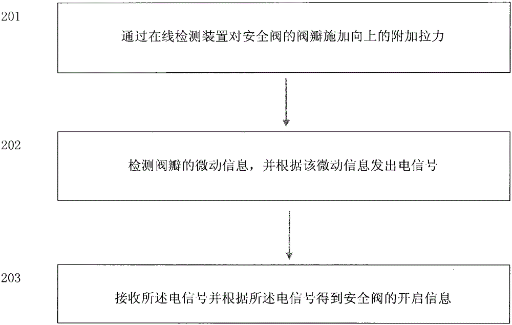
[0055] Such as figure 2 A method for opening a safety valve is shown, comprising the steps of:

[0056] 201. Apply an upward additional pulling force to the disc of the safety valve through an online detection device;

[0057] 202. Detect the micro-movement information in the critical opening state of the valve disc, and send an electrical signal according to the micro-motion information;

[0058] 203. Receive the electrical signal and obtain opening information of the safety valve according to the electrical signal;

[0059] The opening method of the embodiment of the present invention is to detect the micro-movement information in the critical opening state of the valve clack, and generate an electrical signal to obtain the opening information of the safety valve. This method judges whether the safety valve is open or not. It does not need to pull up the valve disc to find the characteristic points on the curve of the applied force changing with time. It only needs to det...

Embodiment 3

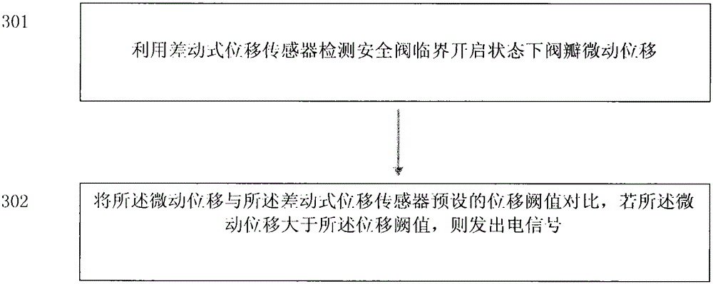
[0115] Such as Figure 10 As shown, this embodiment provides a method for judging the opening of a safety valve, including the following steps:

[0116] 1001, implementing an upward lifting force on the safety valve through a hydraulic method and an online detection device;

[0117] 1002. Use the differential displacement sensor to judge the opening state of the safety valve in the critical opening state, and calculate the actual opening pressure of the safety valve according to the lift force value at this time.

[0118] The opening method of the embodiment of the present invention detects the displacement of the safety valve, and judges whether the safety valve is opened according to the range of the displacement.

[0119] The specific working principle is as follows:

[0120] Consider a spring-loaded safety valve that is closed and functioning properly. Such as Figure 7 As shown, part of the spring preload Fd acting downward on the valve disc is used to resist the forc...


PUM


Abstract

The invention belongs to the field of online testing for a safety valve and a relief valve, and particularly relates to a safety valve online testing device in a continuous production process, an on determining method for the safety valve, and an online testing method. The safety valve online testing device comprises three parts, namely a hydraulic device, a mechanical clamping device and a host computer. The data processing unit of the host computer is connected with a force sensor, a differential type displacement sensor and a sound pickup through sensor information wires. Tested on-and-off change information of the safety valve is simultaneously transmitted to the host computer. Then analysis, data processing and data storage are performed on the measured data. The online testing device has advantages of reasonable mechanical structure, easy operation, accurate on-and-off determination, good man-machine interaction environment and high suitability for an online testing field of the safety valve.

Description

technical field [0001] The invention belongs to the field of on-line detection of safety valves and pressure relief valves, and in particular relates to an on-line detection device for safety valves in a continuous production process, a method for judging and opening the safety valves, and an on-line detection method. Background technique [0002] On-line testing of safety valves is a newly developed specialized technology in the field of safety valves and pressure relief valves, with a history of more than ten years. Since the device does not need to be shut down when detecting and setting the opening pressure of the safety valve on-line, the production continues as usual. Therefore, this technology immediately aroused great interest in the industry as soon as it appeared, especially for modern continuous production such as petrochemical, electric power, and chemical industries. widely used. [0003] Moreover, most of the on-line detection instruments used in industry curr...

Claims


Application Information

Patent Timeline
Patent Type & Authority Applications(China)
IPC IPC(8): G01M13/00
Inventor 李治涛
Owner 李治涛
Why Eureka
Try Eureka