
Satellite antenna ring array deployable unit structure

A technology of unit structure and ring array, which is applied to antennas, folded antennas, antennas suitable for movable objects, etc., can solve the problems of increasing the complexity of the unit mechanism, the overall quality of the mechanism, the increase of basic units, and the complexity of the parts mechanism, etc., to achieve Improved drive mode, good synchronization, and low machining accuracy requirements

Inactive Publication Date: 2015-11-18
NORTHWESTERN POLYTECHNICAL UNIV
View PDF8 Cites 2 Cited by
  • Summary
  • Abstract
  • Description
  • Claims
  • Application Information

AI Technical Summary

Problems solved by technology

Although this type of expandable mechanism has the advantage of large shrinkage ratio, it also has the disadvantages of poor synchronization, large impact, overly complicated mechanism of some parts, high manufacturing cost, and low deployment accuracy.
[0004] In the invention patent 201210021574, a deployable antenna radially arranged along the central axis is proposed. Its advantage is that it can obtain a larger deployment radius, and obtaining a larger deployment radius depends on increasing the number of basic units, and in order to ensure The unit mechanism needs to arrange the same number of units in six directions at the same time, but it increases the complexity of the unit mechanism and the overall quality of the mechanism, which is more difficult in actual operation

Method used


Image

  • Satellite antenna ring array deployable unit structure
  • Satellite antenna ring array deployable unit structure
  • Satellite antenna ring array deployable unit structure

Examples

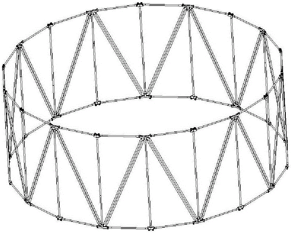

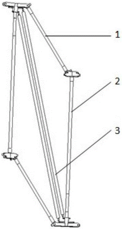
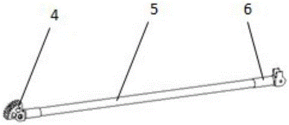
Embodiment Construction

[0027] This embodiment is a deployable unit structure of a satellite antenna circular array.

[0028] refer to Figure 1 to Figure 10 , satellite antenna ring array expandable unit structure, using multiple identical units to form a ring expandable array, adjacent units are connected by a shared middle rod assembly, and the angle between adjacent unit structures is 10° to 160° ; For the requirements of different unit numbers, calculate the angle between adjacent units according to the formula 180°*(n-2) / n.

[0029] The expandable unit structures of the satellite antenna annular array are connected through a common intermediate rod assembly, and each unit structure is identical. Each unit structure includes two horizontal rod assemblies 1, two intermediate rod assemblies 2, and two diagonal rod assemblies 3, and the horizontal rod assembly 1 and the diagonal rod assembly 3 are hinged with the intermediate rod assembly 2 to form a quadrilateral unit mechanism; two Two intermed...


PUM


Abstract

The present invention discloses a satellite antenna ring array deployable unit structure. The ring deployable array is composed of a plurality of same units, each unit consisting of two horizon rod assemblies, two centre rod assemblies and two diagonal rod assemblies which have the same structure; the horizon rod assemblies and the diagonal rod assemblies are hinged to the centre rod assemblies to form a telescopic quadrilateral unit structure; two adjacent units are connected through a common centre rod therebetween; the unit structure may be shrank and deployed by utilizing the proportional relation of the physical dimension; and the deployable ring array only has one degree of freedom so as to easy to be driven and controlled. The deployable ring array provided by the invention has the advantages of good stability in the deploying process, high precision of deploying and good synchronism. The unit structure are characterized by small variety of the parts, low working accuracy requirement and simple and easy assembling, and without changing the structure and the dimension of parts, the amount of the units may be increased or reduced at will according to requirements of different cases and work environments, wherein each part may be reused.

Description

technical field [0001] The invention belongs to the technical field of structural design, and in particular relates to a deployable unit structure of a satellite antenna annular array. Background technique [0002] Antennas are important structural components on satellites. In order to enhance the coverage area and accuracy of the satellite, the antenna must meet a very wide signal receiving frequency band. At the same time, because the signal to be received is very weak, that is, the gain of the antenna is required to be high. The feasible way to meet the requirements is to increase the aperture of the satellite antenna. . At the same time, in order to meet the requirements of multi-function, large capacity, multi-spectrum, high power, and long life of satellites, satellite antennas are required to become larger and more complex, but at the same time, they are faced with limitations in the effective space and carrying capacity of vehicles. The most feasible way to solve i...

Claims


Application Information

Patent Timeline
IPC IPC(8): H01Q1/08H01Q15/16H01Q1/28
Inventor 王三民司艳新郝立峰蔡鑫姜景明陈森陈群
Owner NORTHWESTERN POLYTECHNICAL UNIV
Learn More