
Anchoring nerve block catheter

A nerve block, catheter technology, applied in catheters, spinal cord nerve electrodes, hollow probes, etc., can solve problems such as prolonging hospitalization days, delaying recovery, and increasing the risk of failure

Active Publication Date: 2015-11-18
SRI INTERNATIONAL +2
View PDF10 Cites 3 Cited by
  • Summary
  • Abstract
  • Description
  • Claims
  • Application Information

AI Technical Summary

Problems solved by technology

For example, prolonged femoral nerve block during total knee replacement (TKR) surgery may increase risk of failure, delay recovery and lengthen hospital stay (LHS)
On the other hand, an ineffective femoral nerve block during TKR may also delay recovery, lengthen hospital stay, reduce patient satisfaction and increase hospital costs

Method used


Image

  • Anchoring nerve block catheter
  • Anchoring nerve block catheter
  • Anchoring nerve block catheter

Examples


Embodiment

[0129] Typical usage example: ACL repair. With the previous approach (ie, a single peripheral nerve block), the patient receives a prescribed anesthetic that causes nausea and vomiting and reduces patient satisfaction. Alternatively, nerve blocks (NB) replace anesthesia during surgery. However, these options do not address the need to use physicians, require excessive operating room time, and are costly. Furthermore, current methods involving serial peripheral nerve blocks often require patients to use prescription balloon pumps that have a high failure rate. In contrast, the catheter system described herein reduces the use of balloon pumps and may improve care flow.

[0130] A device according to the present disclosure having Malecott extension when a tissue lock is prepared, implanted, and activated. The force required to remove the catheter from the muscle tissue was significantly higher than expected. In vitro and in vivo experiments, using a tensile testing machine, i...


PUM


Abstract

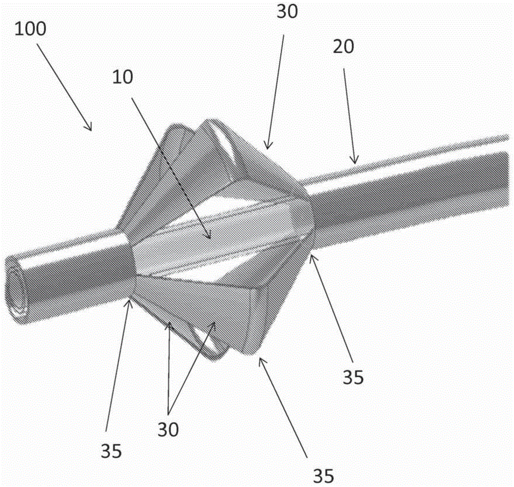
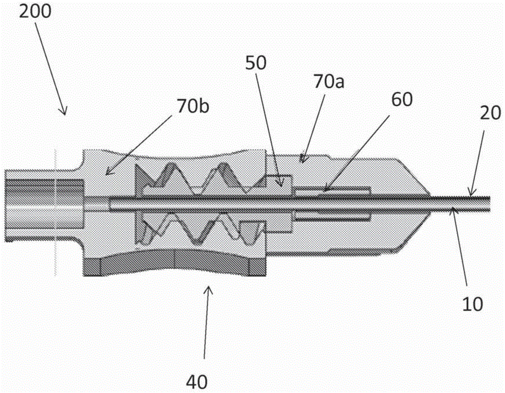
The invention relates to medical devices and, particularly, catheter medical devices. In an aspect is a nerve block catheter system comprising a dual-sheath catheter comprising an inner sheath and an outer sheath, wherein distal ends of the sheaths are connected, the inner sheath defines a fluid delivery lumen, and the outer sheath comprises a tissue lock movable between a collapsed position and an extended position, wherein the tissue lock forms a reversible tissue anchor when in the extended position, and an actuator connected to the proximate end of the catheter and configured to activate the tissue lock by sliding the outer sheath length-wise relative to the inner sheath.

Description

[0001] Inventors: J. Hoffees, M. Kosari, Qiu Chunyuan, P. E. Garcia, and K. S. Koenig, all from Menlo Park, California. [0002] Applicants: Thinking Research (SRI) International Consulting and Consulting Company, Stanford University Trustee Board, and Qiu Chunyuan. [0003] This invention was made with Government support under Department of Health and Human Services (DHHS) / Food and Drug Administration Grant No. 1P50FD003782. The government has certain rights in this invention. [0004] Cross References to Related Applications [0005] This application claims U.S. Application Serial No. 61 / 754,484, filed January 18, 2013, U.S. Application Serial No. 61 / 845,238, filed July 11, 2013, U.S. Application Serial No. 61 / 845,238, filed July 11, 2013 Serial No. 61 / 845,244 and the priority of US Application Serial No. 61 / 845,248, filed July 11, 2013, the disclosure of which is incorporated herein in its entirety. Background technique [0006] Accumulating evidence from animal models t...

Claims


Application Information

Patent Timeline
IPC IPC(8): A61M25/02
CPCA61M25/02A61M19/00A61M25/0026A61M2025/0293A61M25/0017A61M25/0074A61M25/0108A61M25/04A61M25/005A61M2025/0056A61M2202/048A61N1/0551A61M25/0053
Inventor 邱春元J·霍菲斯M·科萨里P·E·加西亚K·S·科尼格
Owner SRI INTERNATIONAL
Learn More