Buck-boost converter with buck-boost transition switching control

一种升压切换、控制器的技术,应用在输出功率的转换装置、控制/调节系统、仪器等方向,能够解决低效率等问题

Active Publication Date: 2015-11-18
TEXAS INSTR INC
View PDF6 Cites 22 Cited by
  • Summary
  • Abstract
  • Description
  • Claims
  • Application Information

AI Technical Summary

Problems solved by technology

Disadvantages of this approach are clock timing, which requires high Iq and lower efficiency at low load currents, and chaotic effects and subharmonic oscillations

Method used


Image

  • Buck-boost converter with buck-boost transition switching control
  • Buck-boost converter with buck-boost transition switching control
  • Buck-boost converter with buck-boost transition switching control

Examples


Embodiment Construction

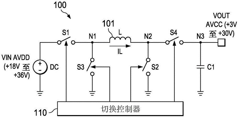
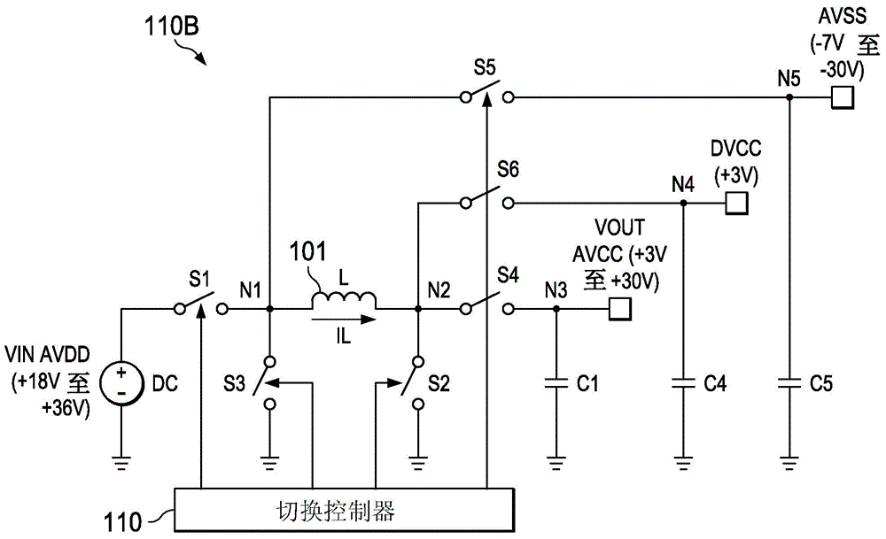
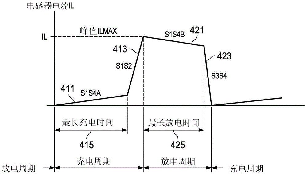
[0022] Buck-boost regulation (switching control) method including buck-boost transition switching control according to the present invention can be adapted for single inductor buck-boost switching conversion operating in DCM (Discontinuous Conduction Mode) regulator / regulator architecture. Converter and regulator are used interchangeably, although in general a regulator includes a converter circuit with appropriate inductors and output capacitors (ie, for typical applications, the inductor and output capacitor will not be integrated with the converter circuit). The converter circuit includes a switching network coupled to the inductor and an associated switching controller, which can be integrated or can be implemented separately from the switching controller, for example implemented as an integrated circuit. To simplify, with Figure 1A / Figure 1B , image 3 and Figure 5A / Figure 5B The accompanying description refers to the illustrated example embodiment as a regula...


PUM


Abstract

A buck-boost regulation methodology operable, in one embodiment, with a single inductor, four-switch (S1-S4) buck-boost regulator configured for DCM. Buck-boost transition switching control is operable when inductor charge time exceeds a max charge time, and inductor discharge time exceeds a max discharge time, and includes: (a) during charge transition cycles, at the end of the max charge time, if IL is less than a predetermined peak current IL—MAX, switching S2 on (grounding the output side of the inductor) and S4 off, causing IL to increase (a rapid S1S2 charging current ramp), until IL reaches IL—MAX, and (b) during discharge transition cycles, at the end of the max charge time, if IL is greater than zero, switching S1 off and S3 on (grounding the input side of the inductor), causing IL to increase (a rapid S3S4 IL discharging current ramp), until IL reaches zero.

Description

technical field [0001] The present application relates generally to buck-boost switching converters / regulators, and more particularly to implementing switching control during buck-boost transitions. Background technique [0002] Buck-boost switching converter topologies generally require some switching control mechanism to ensure proper operation during the transition between buck and boost, when the input and output voltages are close and the load current is low. [0003] A common method is dual-slope PWM (Pulse Width Modulation). Disadvantages of this approach include lower efficiency and larger Iq at the transition region due to commutation of the transition (quiescent current or ground current due to DC bias, ie current not available to the load). [0004] Another common approach is to use a comparator to determine whether the input voltage or the regulated output voltage is greater and control a single switch during the transition. Disadvantages of this approach inclu...

Claims


Application Information

Patent Timeline
Patent Type & Authority Applications(China)
IPC IPC(8): H02M3/158
CPCH02M3/1582
Inventor V·V·伊万诺夫R·帕卡喀什
Owner TEXAS INSTR INC
Why Eureka
Try Eureka