
Cooking robot
A cooking robot and rack technology, applied in the field of kitchen utensils, can solve the problems of poor cooking effect, small pot angle range, uneven heating of ingredients, etc., to achieve good cooking effect, convenient output and processing, and convenient control
- Summary
- Abstract
- Description
- Claims
- Application Information
AI Technical Summary
Problems solved by technology
Method used
Image

Examples
Embodiment Construction
[0038] The following are specific embodiments of the present invention and in conjunction with the accompanying drawings, the technical solutions of the present invention are further described, but the present invention is not limited to these embodiments.
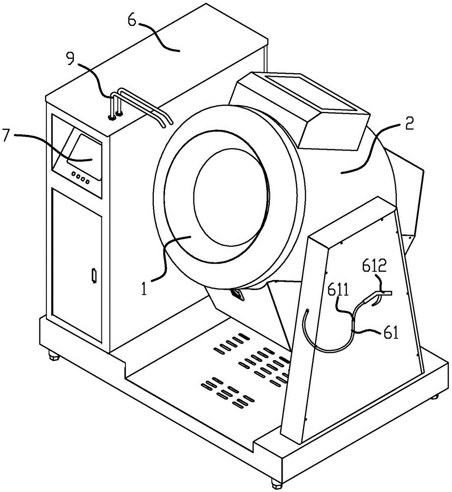
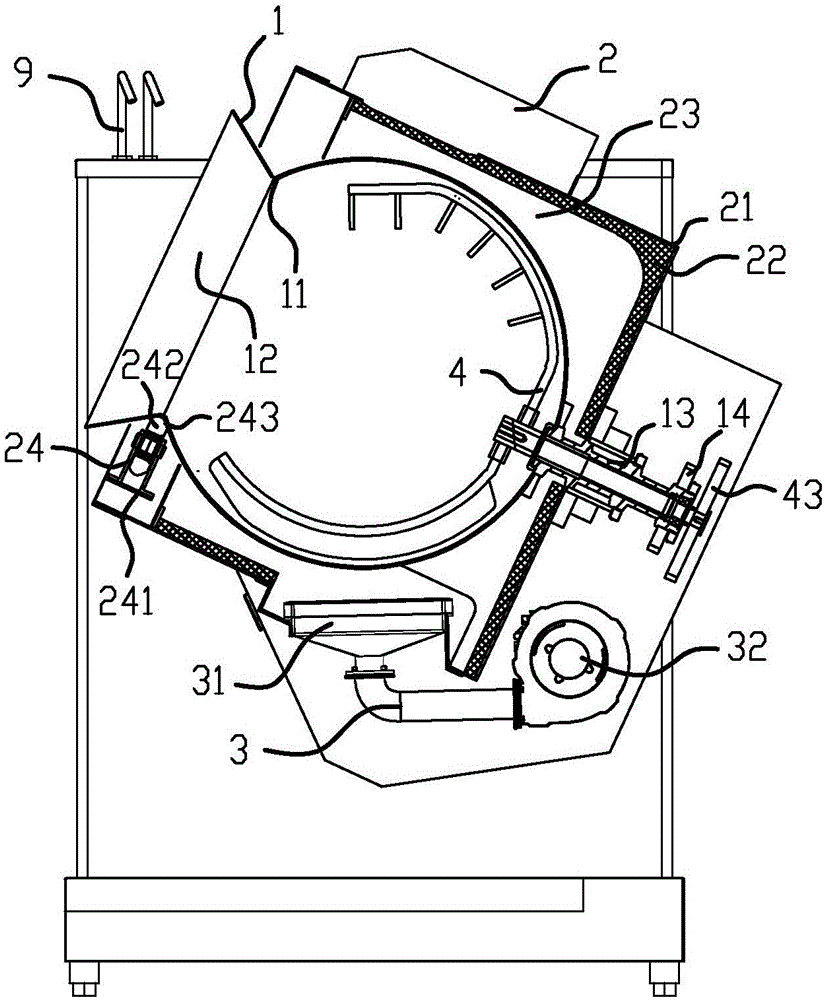
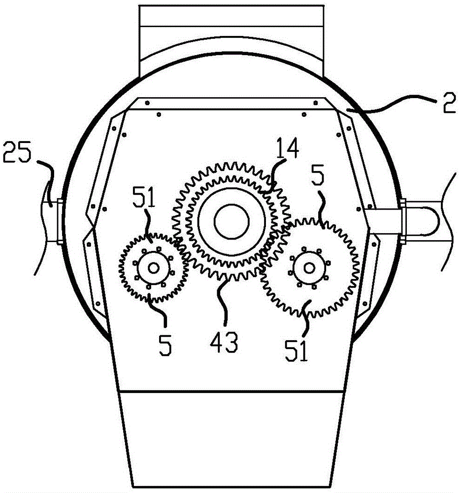
[0039] Such as Figure 1 to Figure 4 As shown, the cooking robot includes: pot body 1, shell 2, heating device 3, manipulator 4, driving device 5, frame 6, control system 7 installed on the frame 6, turning device 8 and feeding device 9, The pot body 1 is spherical, and an opening 11 is provided on the pot body 1, and a connecting rod 13 is fixedly connected to the pot body 1; A heat dissipation channel 23 is formed between the casing 2, the connecting rod 13 penetrates and is installed on the casing 21, and the casing 21 can drive the pot body 1 to move together; the heating device 3 is installed in the casing 2 and is located outside the pot body 1, and the heating device 3 can heat the pot body 1; the manipulator 4 is ...
PUM
 Abstract
Description
Claims
Application Information