Digitized template used for orthognathic surgery and manufacturing method thereof

A technology of orthognathic surgery and guide plate, applied in the field of orthognathic surgery guide plate and its production, can solve the problems of increasing the economic burden of patients, material waste, and high cost of 3D printing

Active Publication Date: 2015-11-25
SICHUAN UNIV
View PDF7 Cites 25 Cited by
  • Summary
  • Abstract
  • Description
  • Claims
  • Application Information

AI Technical Summary

Problems solved by technology

Due to the high cost of 3D printing, and the guide plate used in the operation is a single-use instrument, it will increase the economic burden of the patient and cause waste of materials

Method used


Image

  • Digitized template used for orthognathic surgery and manufacturing method thereof
  • Digitized template used for orthognathic surgery and manufacturing method thereof
  • Digitized template used for orthognathic surgery and manufacturing method thereof

Examples


Embodiment 1

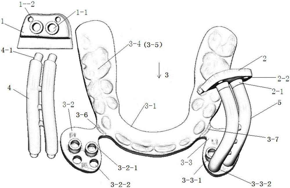
[0077] The digital guide plate used for orthognathic surgery described in this embodiment has a structure such as figure 1 As shown, it includes the occlusal plate 3, the maxillary left positioning plate 1 matching the maxillary left bone surface, and the maxillary right positioning plate 2 matching the maxillary right bone surface, which are used to connect the occlusal plate and the maxillary left positioning The maxillary left connector 4 of the plate is used to connect the bite plate with the maxillary right connector 5 of the maxillary right positioning plate. The occlusal plate 3 is composed of a main board 3-1, a left wing plate 3-2 connected to the left front side of the main board, and a right wing plate 3-3 connected to the right front side of the main board; the upper surface of the main board is provided with an upper dentition terminal occlusal tooth print 3-4, the lower surface of the main board is provided with the final occlusal teeth impression 3-5 of the lowe...

Embodiment 2

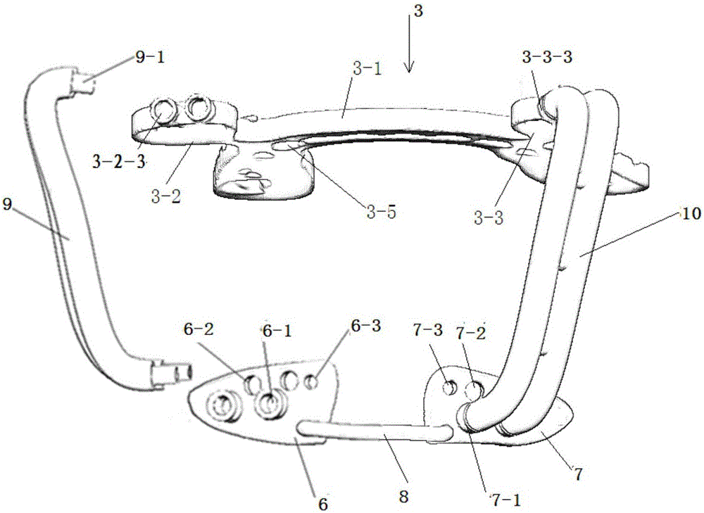
[0091] The digital guide plate used for orthognathic surgery described in this embodiment has a structure such as figure 2As shown, it includes an occlusal plate 3, a left chin positioning plate 6 that matches the left bone surface of the chin, a right chin positioning plate 7 that matches the right bone surface of the chin, and two ends that are respectively connected with the left chin positioning plate, The strip 8 connected to the right positioning plate of the chin, the left connecting piece 9 of the chin used to connect the occlusal plate and the left positioning plate of the chin, the right connecting piece of the chin used to connect the occlusal plate and the right positioning plate of the chin 10. The occlusal plate 3 is composed of a main plate 3-1, a left wing plate 3-2 connected to the left front side of the main plate, and a right wing plate 3-3 connected to the right front side of the main plate; 3-5, the front side of the left wing is provided with a set of s...

Embodiment 3

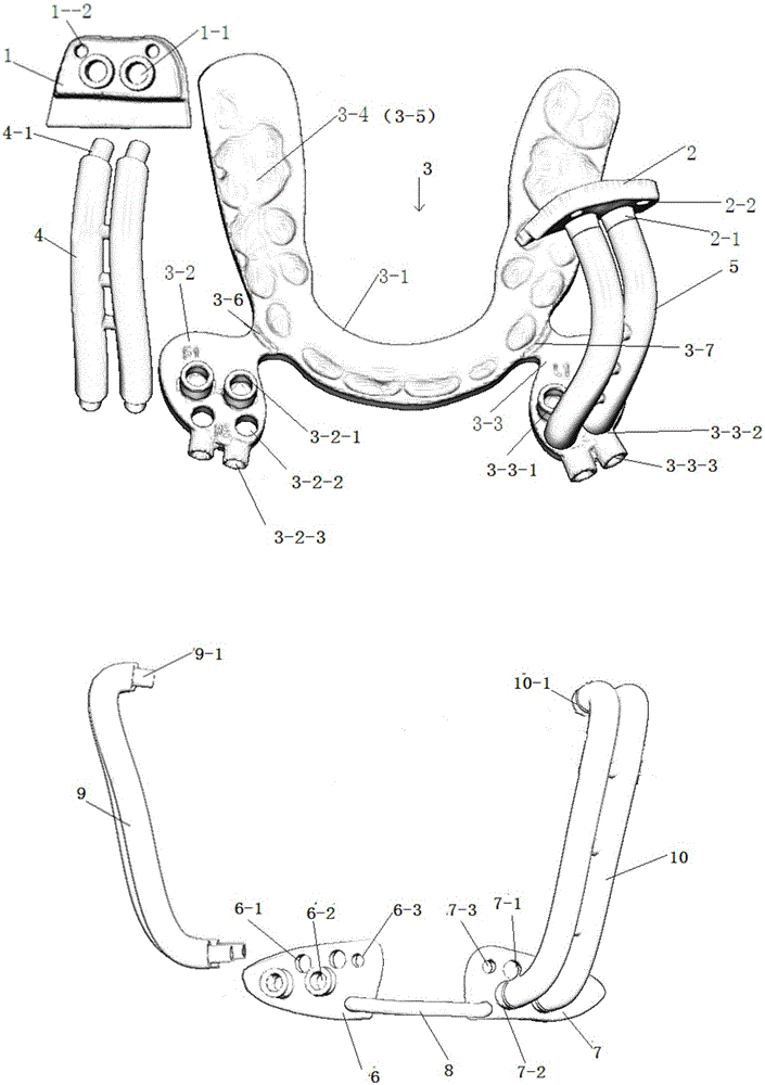
[0104] The digital guide plate used for orthognathic surgery described in this embodiment has a structure such as image 3 As shown, it includes the occlusal plate 3, the maxillary left positioning plate 1 matching the maxillary left bone surface, and the maxillary right positioning plate 2 matching the maxillary right bone surface, which are used to connect the occlusal plate and the maxillary left positioning The maxillary left connecting piece 4 of the plate, the maxillary right connecting piece 5 used to connect the occlusal plate and the maxillary right positioning plate, the left chin positioning plate 6 matching the left bone surface of the chin, and the right chin positioning plate The right chin positioning plate 7 matching the side bone surface, and the strip body 8 connected to the left chin positioning plate and the right chin positioning plate at both ends, are used to connect the occlusal plate and the left chin positioning plate to the left side of the chin The ...


PUM


Abstract

A digitized template used for orthognathic surgery comprises an occlusal splint, a maxilla left positioning plate, a maxilla right positioning plate, a maxilla left side connecting piece and a maxilla right side connecting piece; or comprises an occlusal splint, a chin left positioning plate, a chin right positioning plate, a strip body of which the two ends are respectively connected with the chin left positioning plate and the chin right positioning plate, a chin left side connecting piece and a chin right side connecting piece; or comprises an occlusal splint, a maxilla left positioning plate, a maxilla right positioning plate, a maxilla left side connecting piece, a maxilla right side connecting piece, a chin left positioning plate, a chin right positioning plate, a strip body of which the two ends are respectively connected with the chin left positioning plate and the chin right positioning plate, a chin left side connecting piece and a chin right side connecting piece, wherein the occlusal splint comprises a main plate, a left wing plate connected with the left front side of the main plate, and a right wing plate connected with the right front side of the main plate; all the components are designed through software, and manufactured by adopting a rapid forming method.

Description

technical field [0001] The invention belongs to the field of auxiliary medical devices, in particular to a guide plate for orthognathic surgery and a manufacturing method thereof. Background technique [0002] In the treatment of patients with craniomaxillofacial malformations, surgery is often required to isolate the maxillary, mandibular and / or chin bones, move them into the correct position and fix the bone fragments in that position while establishing a stable bone. The occlusal relationship, such surgery is called orthognathic surgery. For patients who need simultaneous maxillary and mandibular surgery, the position of the maxilla after incision is determined by the position of the mandible before surgery, and the position of the mandible is fixed by the maxilla after moving and fixing the maxilla. The device used to guide the position of the upper and lower jaws during surgery is called a splint, the one used to position the maxilla is called an intermediate splint, a...

Claims


Application Information

Patent Timeline
Patent Type & Authority Applications(China)
IPC IPC(8): A61B19/00
Inventor 罗恩杜文胡静祝颂松李继华林云锋李佳洋
Owner SICHUAN UNIV
Why Eureka
Try Eureka