
Tilting-type automatic coating machine and working method

An automatic coating and tilting technology, applied in the direction of coating, the device for coating liquid on the surface, etc., can solve the problems of liquid and liquid splashing, confinement, and coating liquid splashing outward, so as to improve the drying efficiency and improve the efficiency. , the effect of simple control process

Active Publication Date: 2015-11-25
黄翔鸥
View PDF10 Cites 8 Cited by
  • Summary
  • Abstract
  • Description
  • Claims
  • Application Information

AI Technical Summary

Problems solved by technology

[0002] The tilting automatic coating machine in the prior art, such as the coating machine whose document number is CN203648781U and CN203899846U, after the workpiece in the basket is taken out from the coating solution, in order to make the coating solution thrown out during the drying process can be It is collected and reused. During the drying process, the basket is located above the coating liquid in the liquid storage tank, that is, the drying station and the liquid coating station are at the same station. Since the height above the liquid level of the liquid storage tank is limited and the drying When the motor drives the basket, the rotation speed is fast, and a small amount of liquid still splashes out from the opening of the liquid storage tank; in addition, due to the limitation of the diameter or width of the liquid storage tank, the angle of inclination is limited when it is tilted to dry, Generally, the angle between the maximum tilt and the vertical state is 10-20 degrees, which limits the effect of tilting drying; as the material basket tilting automatic coating machine with the document number CN202079009U, although it can greatly reduce the drying effect in the drying process. Swing, but because it is not equipped with a special drying liquid collection device that matches it, the coating liquid will splash outward during the drying process

Method used


Image

  • Tilting-type automatic coating machine and working method
  • Tilting-type automatic coating machine and working method
  • Tilting-type automatic coating machine and working method

Examples


Embodiment Construction

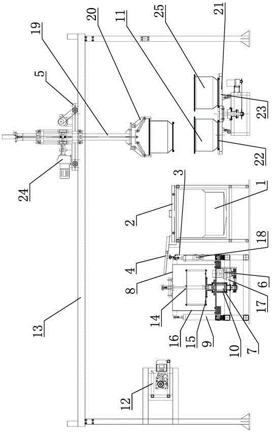
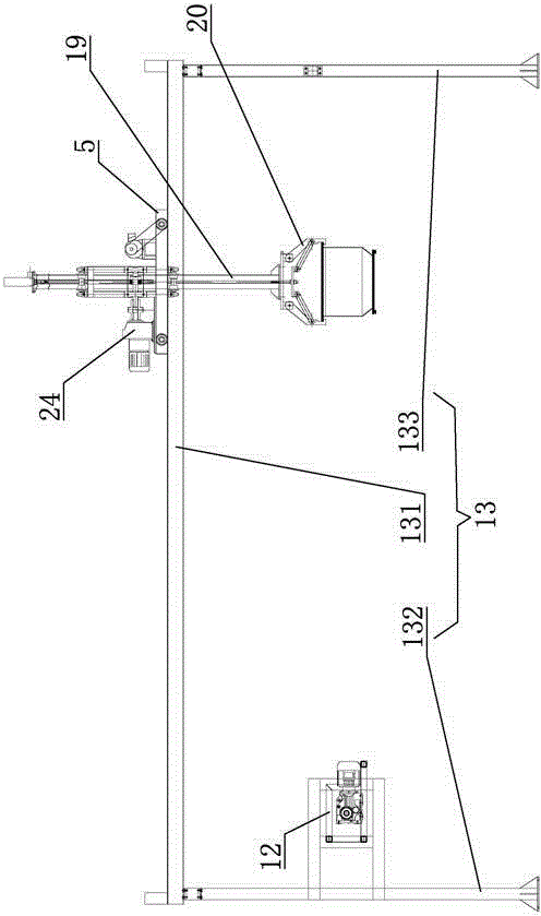
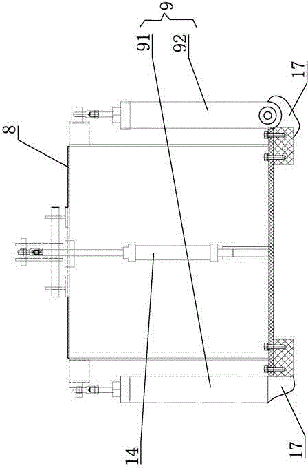
[0037] Such as Figure 1-7 As shown, the inclined automatic coating machine of the present invention includes: liquid coating tank 1, liquid coating tank cover 2, cylinder 3, transition plate 4, trolley 5, reduction motor 6, transmission shaft 7, cylinder cover 8, swing hydraulic cylinder 9. Shaft sleeve 10, basket one 11, turnover mechanism 12, walking frame 13, hydraulic cylinder 14, spin bracket 15, spin slot 16, base 17, hinge 18, lift cylinder 19, manipulator 20, rotating tray 21. Grabbing station 22, waiting station 23, lifting motor 24, basket two 25.

[0038] The coating liquid tank 1 for holding the coating liquid has an opening facing upward and a coating liquid tank cover 2 is provided on the top. The coating liquid tank 1 is provided with a transition plate 4 on the upper left side. The transition plate 4 is composed of a transition plate 41 that is hinged to each other. The bottom of the second transition plate 42 is fixedly connected to the left edge of the coating...


PUM


Abstract

The invention relates to a tilting-type automatic coating machine and a working method. The tilting-type automatic coating machine comprises a spin-drying tank, wherein the top of the spin-drying tank is open. The spin-drying tank is arranged on a fixed base through a tilting driving mechanism. A cylinder cover capable of being opened and closed is arranged at the top of the spin-drying tank. A spin-drying bracket capable of limiting a basket containing a workpiece is in running fit with the interior of the spin-drying tank. The spin-drying bracket is in transmission connection with a power device arranged at the bottom of the spin-drying tank. The power device is suitable for driving the spin-drying bracket to rotate. The tilting driving mechanism is suitable for driving the spin-drying tank to swing in a reciprocating mode relative to the position perpendicular to the centerline. A coating liquid tank used for storing coating liquid and coating the workpiece is further arranged on one side of the spin-drying tank. A conveying device used for conveying the basket is arranged above the spin-drying tank and the coating liquid tank. By the adoption of the basket conveying device, the spin-drying station is separated from the liquid coating station; during spin-drying, the coating liquid can be prevented from splashing out, and the spin-drying tilting angle is also increased.

Description

Technical field [0001] The invention relates to an inclined automatic coating machine and a working method for automatic coating of workpieces. Background technique [0002] The inclined automatic coating machine in the prior art, such as the coating machine with document number CN203648781U and CN203899846U, when the workpiece in the basket is taken out of the coating liquid, in order to make the coating liquid thrown out during the spin-drying process energy It is collected and reused. The basket is located above the coating liquid in the liquid storage tank during the drying process, that is, the drying station and the coating liquid station are at the same station, because the height above the liquid level of the storage tank is limited and the drying When drying, the motor drives the basket to rotate faster, and there is still a small amount of liquid splashing from the opening of the liquid storage tank; in addition, due to the diameter or width of the liquid storage tank, ...

Claims


Application Information

Patent Timeline
Patent Type & Authority Applications(China)
IPC IPC(8): B05C9/12B05C11/08
Inventor 黄翔鸥
Owner 黄翔鸥
Learn More