Ultrasonic damage-free descaling machine used for cleaning oilfield equipment unit
The technology of oil field equipment and descaling machine is applied in the direction of using liquid cleaning method, cleaning method and utensils, chemical instruments and methods, etc., which can solve the problems of low working efficiency of cleaning equipment, achieve the goal of reducing workload and improving work efficiency Effect
- Summary
- Abstract
- Description
- Claims
- Application Information
AI Technical Summary
Problems solved by technology
Method used
Image

Examples
specific Embodiment approach 1
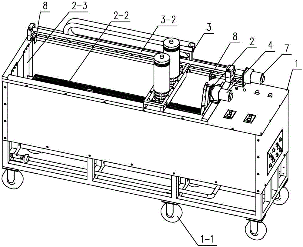
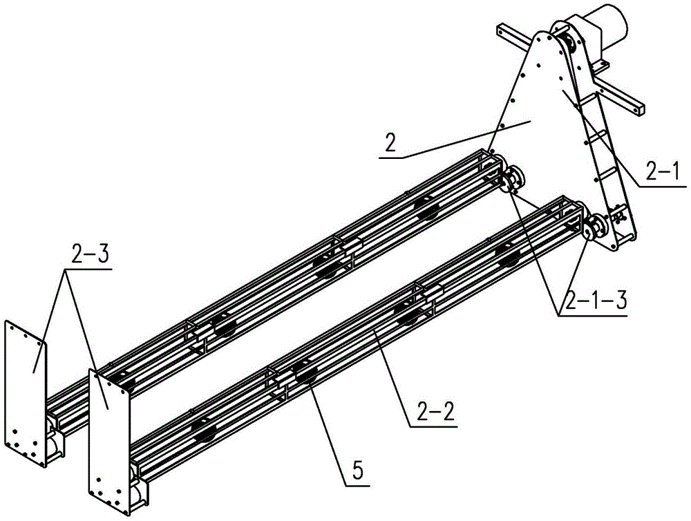
[0014] Specific implementation mode one: combine Figure 1 to Figure 4 To illustrate, an ultrasonic non-destructive descaling machine for cleaning oilfield equipment components described in this embodiment includes an ultrasonic cleaning tank 1, a rotating mechanism 2 and a mobile energy-concentrating transducer mechanism 3, and the rotating mechanism 2 is arranged at the bottom of the ultrasonic cleaning tank 1 Inside, the mobile energy-concentrating transducer mechanism 3 is suspended on the upper end of the notch of the ultrasonic cleaning tank 1 through the transducer bracket 6, and the rotating mechanism 2 includes a drive assembly 2-1, a cage support 2-3 and a plurality of cages 2-2, the net cage support 2-3 is fixed at the rear end of the ultrasonic cleaning tank 1, the drive assembly 2-1 is fixed at the front end of the ultrasonic cleaning tank 1, and multiple net cages 2-2 are arranged horizontally, each net cage One end of 2-2 is arranged on the net cage support 2-3 ...
specific Embodiment approach 2
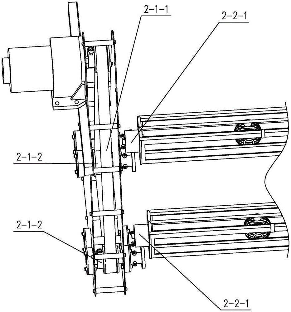
[0016] Specific implementation mode two: combination Figure 1 to Figure 4 Illustrate, the other end of net box 2-2 described in the present embodiment is provided with driven gear 2-2-1, and drive assembly 2-1 comprises driving shaft, synchronous belt 2-1-1, multiple driven shafts, multiple A synchronous wheel 2-1-2 and a plurality of driving gears 2-1-3, the speed regulating motor 4 is connected with the driving shaft, the driving shaft is provided with a driving wheel, and each driven shaft is fixedly connected with a synchronizing wheel 2 respectively. -1-2 and a driving gear 2-1-3, the driving wheel is connected with two synchronous wheels 2-1-2 by a synchronous belt 2-1-1, and the driven gear 2 at the other end of each cage 2-2 -2-1 are respectively meshed with a driving gear 2-1-3. Other compositions and connection methods are the same as those in Embodiment 1.
[0017] Such a design drives the driving shaft to rotate through the speed regulating motor 4, and the driv...
specific Embodiment approach 3
[0018] Specific implementation mode three: combination Figure 1 to Figure 4 Illustrate that the mobile energy-gathering transducer mechanism 3 described in this embodiment also includes two travel switches 3-4. Both ends are provided with stopper 8, and the position of stopper 8 corresponds to travel switch 3-4. Other compositions and connection modes are the same as those in Embodiment 1 or 2.
[0019] In such a design, the travel switch 3-4 is installed at the front and rear ends of the transducer bracket 6. When the energy-gathering transducer 3-1 moves to the front and rear ends of the ultrasonic cleaning tank 1, it touches the corresponding stopper 8, so that the energy-gathering transducer 3-1 The energy transducer 3-1 automatically turns around and does reciprocating motion, avoiding the movement of the energy gathering transducer 3-1 exceeding the stroke of the lead screw 3-2 due to the stepping motor 7 control failure.
PUM
 Abstract
Description
Claims
Application Information
 - R&D
- Intellectual Property
- Life Sciences
- Materials
- Tech Scout
- Unparalleled Data Quality
- Higher Quality Content
- 60% Fewer Hallucinations
Browse by: Latest US Patents, China's latest patents, Technical Efficacy Thesaurus, Application Domain, Technology Topic, Popular Technical Reports.
© 2025 PatSnap. All rights reserved.Legal|Privacy policy|Modern Slavery Act Transparency Statement|Sitemap|About US| Contact US: help@patsnap.com