
Metal mold low-pressure casting mold for lower box body of high-speed train cast aluminum gearbox

A high-speed train and low-pressure casting technology, which is applied in the field of high-speed train cast aluminum gearbox casting, can solve the problems of incomplete molding, sand core casting process that is difficult to meet special performance, and high labor intensity.

Active Publication Date: 2015-11-25
LAIAN KELAIXING IND CO LTD
View PDF8 Cites 9 Cited by
  • Summary
  • Abstract
  • Description
  • Claims
  • Application Information

AI Technical Summary

Problems solved by technology

[0003] At present, the sand casting process is adopted for cast aluminum gearboxes at home and abroad, but in actual production, it is found that the use of sand core casting has low productivity, harsh production environment, high labor intensity, high scrap rate and serious waste of resources. Casting defects such as unstable mechanical properties of the alloy, poor product appearance quality, poor dimensional consistency, serious sand loss in the labyrinth oil tank, and incomplete molding
Therefore, the sand core casting process is difficult to meet the special properties of high-speed train gearbox boxes, so it is very important to develop a casting mold that can meet the requirements of high-speed train gearbox boxes.

Method used


Image

  • Metal mold low-pressure casting mold for lower box body of high-speed train cast aluminum gearbox
  • Metal mold low-pressure casting mold for lower box body of high-speed train cast aluminum gearbox
  • Metal mold low-pressure casting mold for lower box body of high-speed train cast aluminum gearbox

Examples


Embodiment Construction

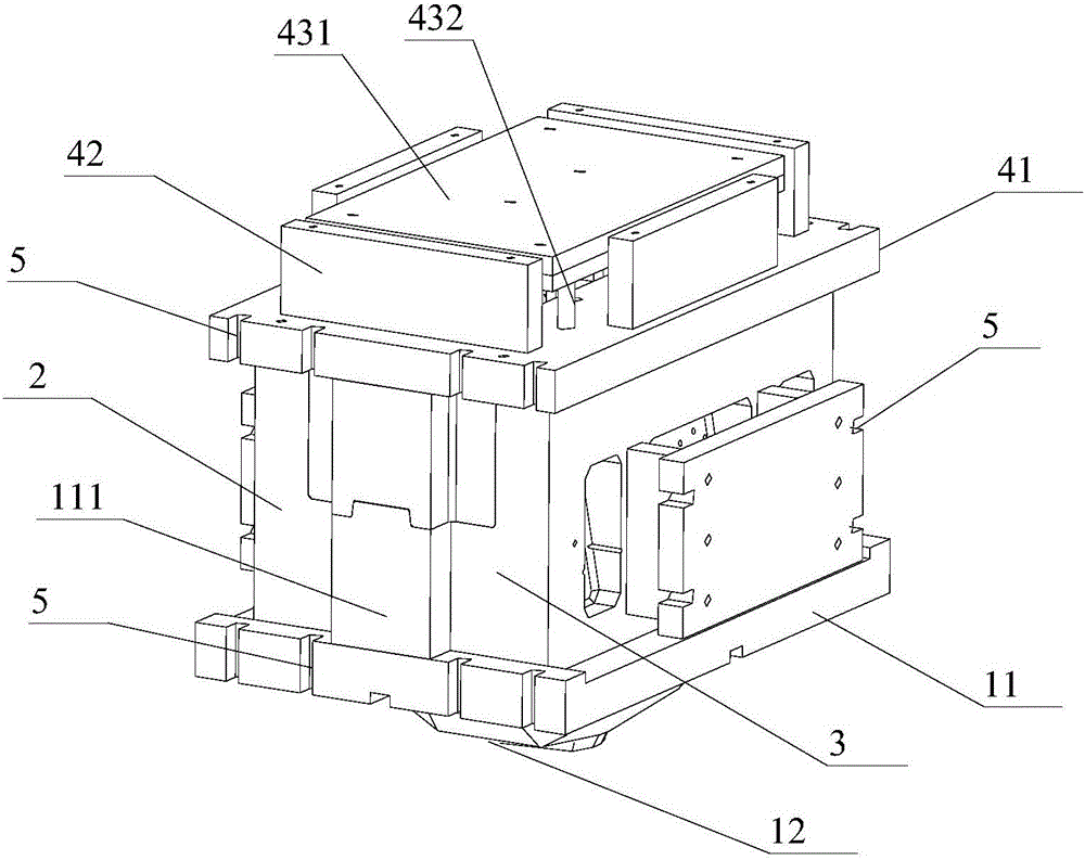
[0030] refer to figure 1 , the present invention proposes a low-pressure casting mold for the metal mold of the lower box of a high-speed train cast aluminum gearbox, including a lower mold, an upper mold, a first slider 2, a second slider 3, a lower mold, an upper mold, and a first slider 2. A casting cavity is formed between the second sliders 3 .

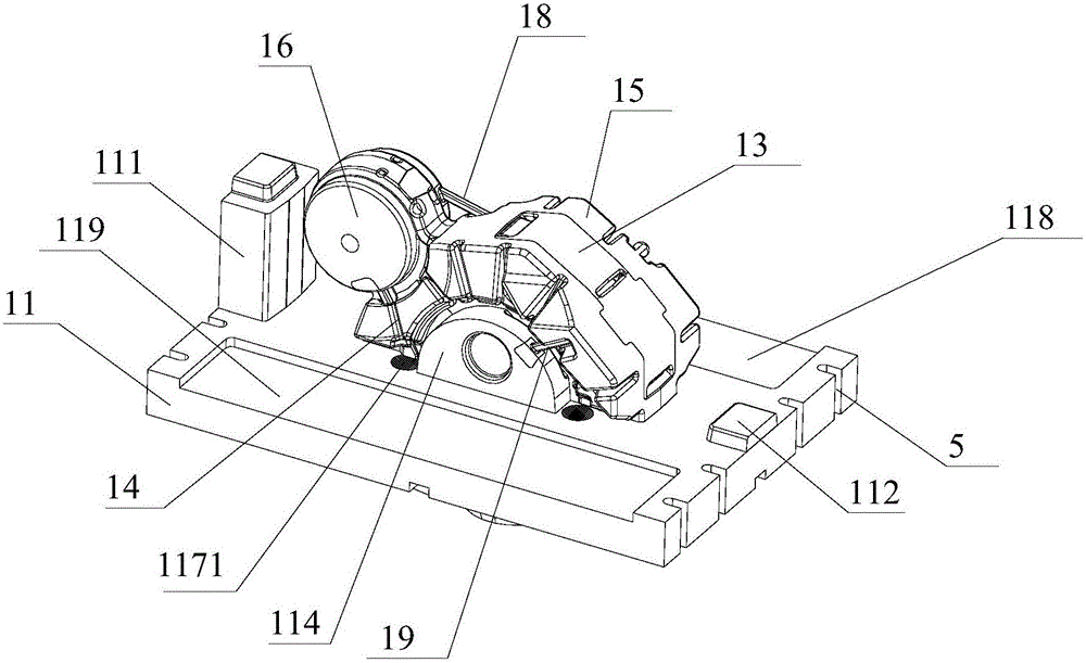
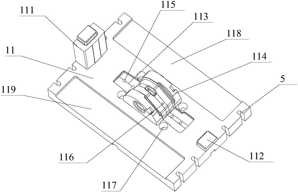
[0031] Such as figure 2 , image 3 , Figure 8 , Figure 11As shown, the lower mold in the present embodiment includes a lower mold base 11 and a sand core, and one side of the lower mold base 11 is provided with a rising liquid gate basin 12, and a splitter plate 17 is arranged in the rising liquid gate basin 12; the lower mold base 11 A sand core positioning groove 113, a first slider positioning groove 118, a second slider positioning groove 119 and a sand core positioning groove 113 are symmetrically arranged on both sides of the sand core positioning groove 113 on the side away from the rising liquid gate basin 12. San...


PUM


Abstract

The invention provides a metal mold low-pressure casting mold for a lower box body of a high-speed train cast aluminum gearbox. The metal mold low-pressure casting mold comprises a lower mold, an upper mold, a first sliding block and a second sliding block. A casting cavity is defined by the lower mold, the upper mold, the first sliding block and the second sliding block. A sand core positioning groove is formed in the side, away from a liquid rise pouring basin, of a lower mold base. A first limiting block and a second limiting block are arranged at the two ends of the sand core positioning groove in the extension direction respectively. The first sliding block and the second sliding block are symmetrically arranged on the two sides of a sand core. A first forming convex block matched with the sand core is arranged on the side, close to the sand core, of the first sliding block. A second forming convex block matched with the sand core is arranged on the side, close to the sand core, of the second sliding block. The upper mold comprises an upper mold base. The upper mold base is provided with a forming groove matched with the sand core. The upper mold is connected with the first limiting block and the second limiting block in a clamped manner through a first limiting block clamping groove and a second limiting block clamping groove. Produced castings are compact in structure, clear in contour, stable in mechanical performance and high in casting yield, and the inner surfaces and the outer surfaces of the castings are smooth.

Description

technical field [0001] The invention relates to the technical field of high-speed train cast aluminum gearbox casting, in particular to a high-speed train cast aluminum gearbox lower box metal mold low-pressure casting mold. Background technique [0002] With the global energy problem and the deteriorating living environment of human beings, in the face of increasingly serious traffic congestion on roads, and aviation concerns about high oil prices, high-speed railways are fast, with large carrying capacity, low energy consumption, low cost, and popular green and environmentally friendly travel transportation Tools are evolving at a rapid pace. The improvement of speed means the improvement of technology. In recent years, in order to achieve the purpose of reducing the weight of vehicles, high-strength cast aluminum alloys have been successfully used for high-speed train gearboxes at home and abroad to replace traditional cast iron alloys. Compared with the traditional cast...

Claims


Application Information

Patent Timeline
IPC IPC(8): B22D18/04
Inventor 周永清渠晓冬邹军
Owner LAIAN KELAIXING IND CO LTD
Learn More