Device and method measuring high rotating speed/superhigh rotating speed three dimensional cutting force

A high-speed, cutting-force technology, used in measuring/indicating equipment, metal processing machinery parts, metal processing, etc., to solve problems such as distortion

Inactive Publication Date: 2015-11-25
TIANJIN UNIV OF TECH & EDUCATION TEACHER DEV CENT OF CHINA VOCATIONAL TRAINING & GUIDANCE
View PDF0 Cites 3 Cited by
  • Summary
  • Abstract
  • Description
  • Claims
  • Application Information

AI Technical Summary

Problems solved by technology

[0008] The present invention is based on cutting processing technology, cantilever beam dynamics inversion technology and strain gauge testing technology, aiming at the lack of distortion in the cutting force signal acquisition process in the current high-speed and ultra-high-speed milling processing, a dynamic inversion method is proposed The method of solving the three-dimensional cutting force in the milling process, and designed a new high natural frequency three-dimensional cutting force test device, which can realize the acquisition and measurement of three-dimensional cutting force under high-frequency cutting processing conditions such as high speed and ultra-high speed

Method used


Image

  • Device and method measuring high rotating speed/superhigh rotating speed three dimensional cutting force

Examples


Embodiment Construction

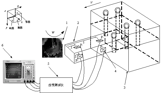
[0012] The structure, working principle and solution process of the present invention will be described in detail below in conjunction with the accompanying drawings.

[0013] As shown in the figure, the present invention provides a high-speed / ultra-high-speed three-dimensional dynamic cutting force test device and method. The test platform mainly consists of a milling cutter 1, a workpiece to be cut 2, a fixed platform 3, a resistance strain gauge 4, a The tester 5 and the oscilloscope 6 are composed. The milling cutter 1 is installed on the main shaft of the machine tool and rotates with the main shaft of the machine tool at a high speed / ultra high speed. The workpiece 2 to be cut is fixed on the fixed platform 3 through bolt compression, and moves horizontally on the moving platform of the machine tool along with the fixed platform 3 . Resistance strain gauge 4 (P 1 ,P 2 ,P 3 ,P 4 ) pasted on the upper and side surfaces of the workpiece 2 to be cut, the distance betwee...


PUM


Abstract

The invention discloses a device and method using dynamics reverse engineering technology to obtain three dimensional cutting force; the device comprises a cantilever structure and a fixing device suitable for cutting process under a high rotating speed/superhigh rotating speed condition, a resistance foil gauge and strain gauge measuring workpiece surface deformation, and an oscilloscope displaying workpiece surface stress and frequency. The cantilever beam surface stress obtained by the resistance foil gauge can be converted into three dimensional cutting force size and frequency through mechanics of materials and cantilever beam dynamics knowledge. The device and method can use dynamics reverse engineering technology to measure three dimensional cutting force; the device is clear in principle, simple in device, high in measure precision, wide in application scope, can measure cutting force size and frequency under the high rotating speed/superhigh rotating speed processing condition, thus solving the problems that an existing dynamometer under high rotating speed/superhigh rotating speed condition is small in fixed frequency, and distorted in signal.

Description

technical field [0001] The invention relates to a device and method for measuring metal cutting force, which belongs to the research field of metal cutting removal mechanism. Background technique [0002] Cutting force is one of the important state parameters in the process of metal cutting, and it is an important research object in the study of metal cutting mechanism and technology application. The acquisition of accurate cutting force signal is an important prerequisite for cutting force analysis. Accurate evaluation is crucial. [0003] At present, the devices for measuring cutting force are: mechanical dynamometer, hydraulic dynamometer, inductive dynamometer, capacitance dynamometer, resistance strain gauge and piezoelectric dynamometer, and the most widely used one is the pressure gauge. Electrical dynamometers and resistance strain dynamometers. [0004] (1) Piezoelectric dynamometer. [0005] Piezoelectric dynamometers are based on the principle of piezoelectric ...

Claims


Application Information

Patent Timeline
Patent Type & Authority Applications(China)
IPC IPC(8): B23Q17/09
CPCB23Q17/099B23Q2717/006
Inventor 张涛阎兵戚厚军李国和霍文国刘洁刘梦莹
Owner TIANJIN UNIV OF TECH & EDUCATION TEACHER DEV CENT OF CHINA VOCATIONAL TRAINING & GUIDANCE
Why Eureka
Try Eureka