
Grinding accessory, swing power tool and application thereof

A technology for oscillating power tools and accessories, applied in grinding tools, grinding devices, grinding machine tools, etc., can solve the problems of workpieces that cannot grind concave curved surfaces, complex structures, etc., and achieve high fit, simple and compact structure, and tight fit. Effect

Inactive Publication Date: 2015-11-25
POSITEC POWER TOOLS (SUZHOU) CO LTD
View PDF6 Cites 0 Cited by
  • Summary
  • Abstract
  • Description
  • Claims
  • Application Information

AI Technical Summary

Problems solved by technology

[0006] In this kind of abrasive belt grinding tool, since the abrasive belt needs to be driven by the driving roller to rotate, the driving roller and driven roller arranged on the working head cause the structure of the working head to be complicated, and the grinding tool is only suitable for Convex surfaces can be ground while workpieces with concave surfaces cannot be ground

Method used


Image

  • Grinding accessory, swing power tool and application thereof
  • Grinding accessory, swing power tool and application thereof
  • Grinding accessory, swing power tool and application thereof

Examples


Embodiment approach 1

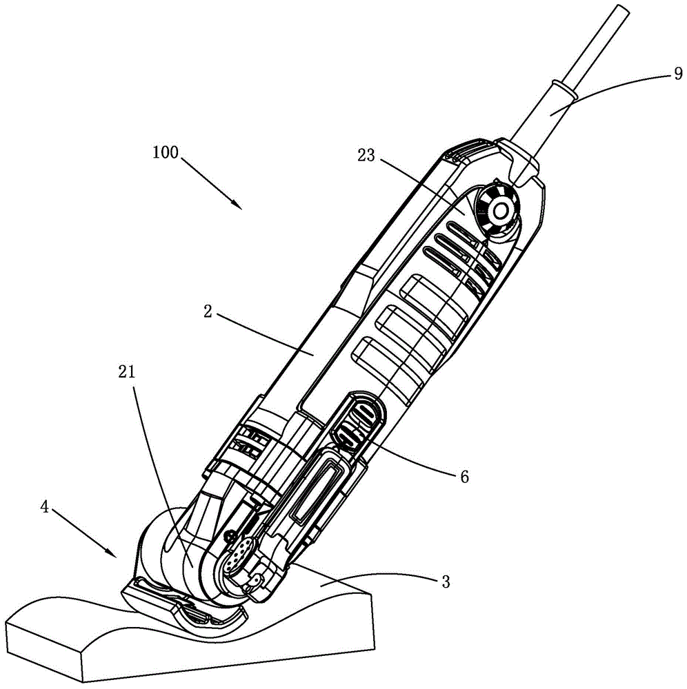
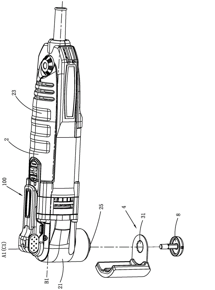
[0046] See figure 1 with figure 2 As shown, Embodiment 1 provides an oscillating power tool 100 equipped with a grinding accessory 4, which can be used for grinding workpieces 3 with curved surfaces, especially for grinding workpieces with concave surfaces.

[0047] The oscillating power tool 100 includes: a housing 2 , a motor (not shown), a transmission mechanism (not shown), and a grinding attachment 4 . Wherein, the casing 2 extends along the longitudinal direction, has a longitudinal axis B1, defines figure 1 In the oscillating power tool 100 shown in , the side close to the grinding attachment 4 in the direction of the longitudinal axis B1 is referred to as "front", and the side away from the grinding attachment 4 is referred to as "rear".

[0048] The housing 2 includes a head shell 21 located at the front of the oscillating power tool 100 and a tail shell 23 disposed at the rear of the head shell 21 . The motor is arranged inside the tail case 23, and the transmiss...

Embodiment approach 2

[0067] Embodiment 2 of the present invention discloses an oscillating power tool 200 equipped with a grinding accessory 40 .

[0068] see Figure 5 As shown, the oscillating power tool 200 is basically the same as the oscillating power tool 200 in the first embodiment, the difference is the grinding part 42 of the grinding attachment 40 .

[0069] The grinding attachment 40 is connected to the output shaft of the oscillating power tool 200 through a locking member 46 . The grinding part 42 has a mounting surface 44 for mounting grinding parts. The mounting surface 44 is a curved surface with a generatrix 45 inside the curved surface. The mounting surface 44 can be regarded as being formed by extending the generatrix 45 along a curve 47, and the curve 47 is the movement of the generatrix 45. track line. Preferably, the busbar 45 is a straight line, and the busbar 45 is parallel to the axis A1 of the output shaft. The transmission part 41 is disposed at one end of the grindin...


PUM

PropertyMeasurementUnit
Lengthaaaaaaaaaa

Abstract

The invention relates to a grinding accessory, and the grinding accessory can be installed on a swing power tool detachably. The swing power tool comprises a head casing and an output shaft which extends out from the interior of the head casing and is provided with a center axis, and the output shaft can rotate and swing around the center axis. The grinding accessory comprises a transmission portion and a grinding portion, one end of the transmission portion is connected to the output shaft, the grinding portion is connected to the other end of the transmission portion, the grinding portion is provided with an installation surface used for the installation of a grinding member, and the installation surface is a curved surface. The invention also relates to a swing power tool provided with the grinding accessory, and the application of the a swing power tool.

Description

technical field [0001] The invention relates to a grinding accessory, in particular to an accessory detachably installed on a hand-held oscillating power tool capable of outputting rotation and reciprocating motion. [0002] The invention also relates to an oscillating power tool and its use. Background technique [0003] The multi-function machine is a common oscillating power tool in the industry. Because its output shaft oscillates around the axis, when different attachment heads are installed on the output shaft, it can realize many different functions, such as sawing, Cutting, grinding, scraping, etc. to suit different work needs. [0004] Grinding is also one of the common means of operation. Usually, a grinding tool with a triangular or quadrangular ground is fixed on the output shaft capable of outputting rotation and reciprocating motion. The grinding tool has a grinding surface and is set at the center of the output shaft. On the vertical face of the line, the sa...

Claims


Application Information

Patent Timeline
IPC IPC(8): B24B37/11B24B37/34B24B37/00
Inventor 王勇钱富
Owner POSITEC POWER TOOLS (SUZHOU) CO LTD
Learn More