Large-tolerance mini-sized end effector having electromechanical output function
An end effector and large-tolerance technology, applied in manipulators, manufacturing tools, chucks, etc., can solve problems such as poor operability, no electrical output, and large energy consumption, and achieve strong interchangeability of parts, long battery life, and The effect of low control precision
- Summary
- Abstract
- Description
- Claims
- Application Information
AI Technical Summary
Problems solved by technology
Method used
Image
Examples
specific Embodiment approach 1
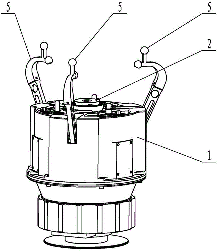
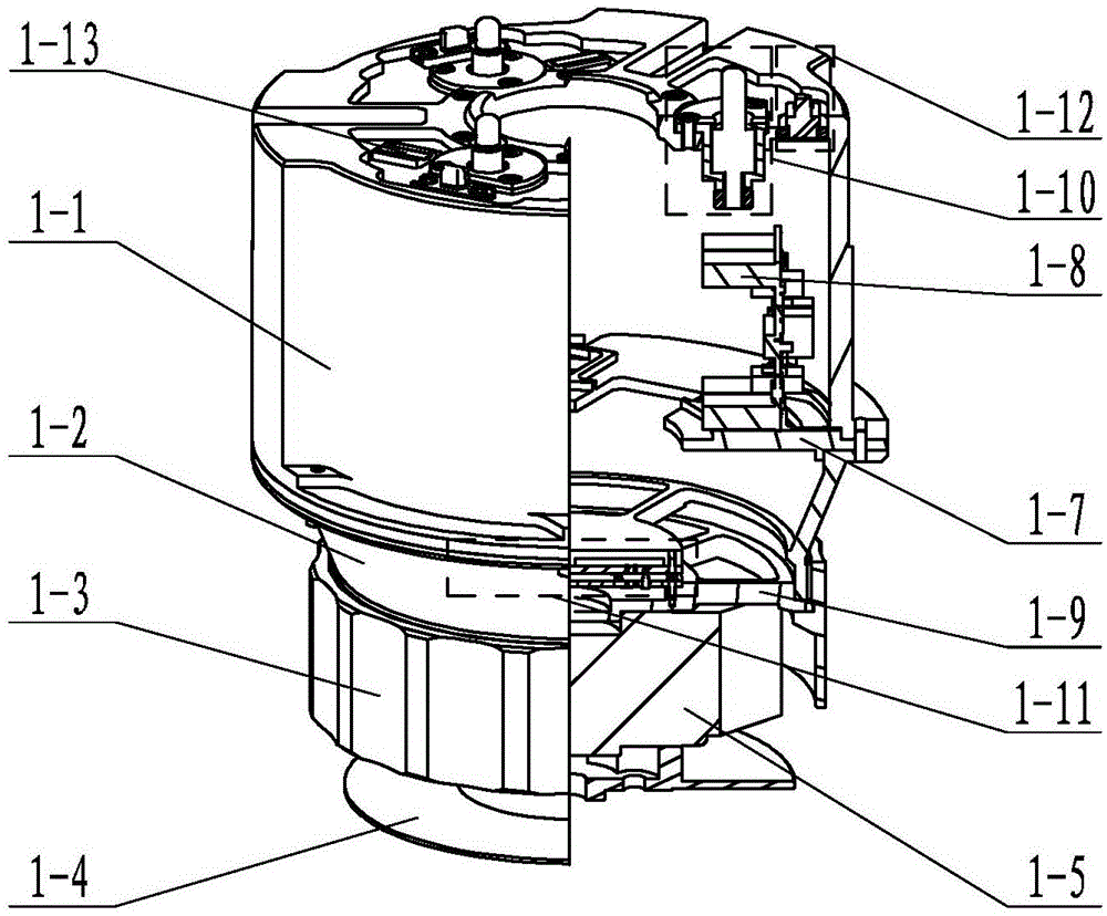
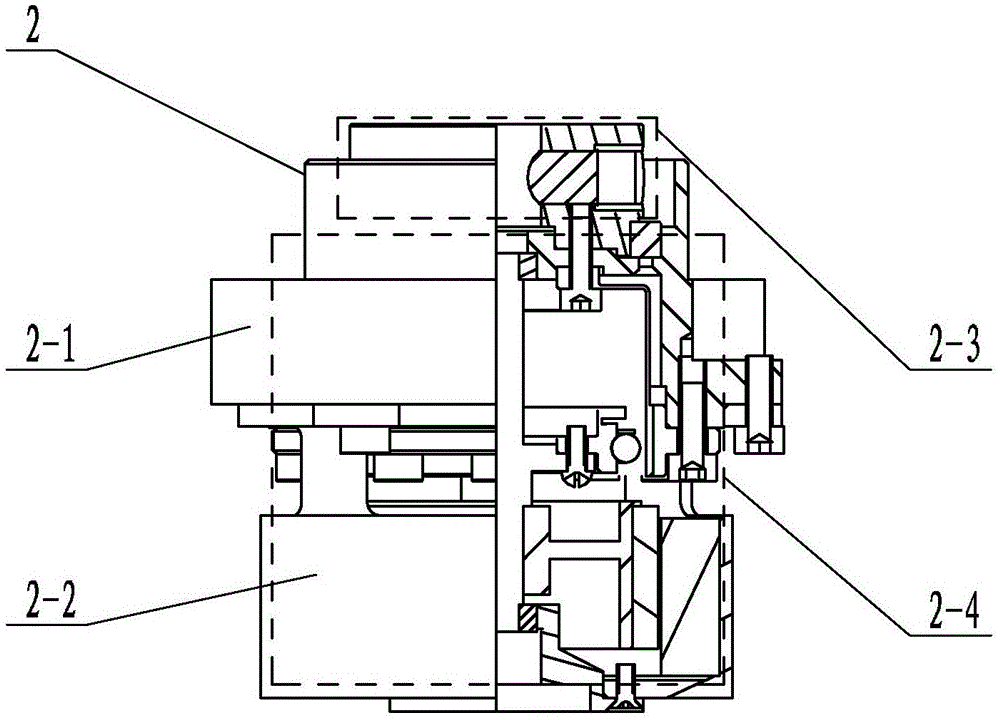
[0035] Specific implementation mode one: combine figure 1 , figure 2 , image 3 , Figure 4 , Figure 5 , Image 6 , Figure 7 , Figure 8 , Figure 9 with Figure 10 Describe this embodiment, this embodiment includes a shell module 1, a power output module 2, a sensor module 3, a motion drive module 4 and a plurality of capture kinematic chains 5;
[0036] The shell module 1 includes a kinematic chain shell 1-1, a drive shell 1-2, a threaded fixed shell 1-3, a mechanical arm connector 1-4, a six-dimensional sensor 1-5, a motion fixing seat 1-7, and a circuit board 1-8, connectors 1-9 for six-dimensional sensors, electrical quick-connect components 1-11, multiple positioning release components 1-10, multiple electrical output components 1-12 and multiple connection detection components 1-13;
[0037]The kinematic chain housing 1-1, the driving housing 1-2, the threaded fixing housing 1-3 and the mechanical arm connector 1-4 are sequentially connected from top to bott...
specific Embodiment approach 2
[0040] Specific implementation mode two: combination figure 1 , Figure 4 with Figure 5 Describe this embodiment, in this embodiment, each capture kinematic chain 5 includes a combined link kinematic chain assembly 5-1, capture finger 5-2, fixed hinge seat 5-3, connecting rod output hinge shaft 5-4, cam hinge The shaft 5-5 and the connecting rod fix the hinge shaft 5-7, the fixed hinge seat 5-3 is fixedly connected to the motion fixed seat 1-7, and the combined link kinematic chain assembly 5-1 is arranged on the motion drive module 4 Between the connecting rod and the fixed hinge shaft 5-7, the output end of the combined link kinematic chain assembly 5-1 is hinged with the catching finger 5-2 through the connecting rod output hinge shaft 5-4, and the catching finger 5-2 is processed with The line chute 5-2-1, the cam hinge shaft 5-5 horizontally passes through the line chute 5-2-1 and is fixedly connected to the fixed hinge seat 5-3;
[0041] The combined link kinematic c...
specific Embodiment approach 3
[0042] Specific implementation mode three: combination Figure 5 to Figure 10 Describe this embodiment. In this embodiment, the motion drive module 4 includes a rocker power module 4-1 and a plurality of output rocker modules 4-2. 1 as the center and evenly distributed around the rocker power module 4-1;
[0043] The rocker power module 4-1 includes a support 4-1-1, a worm 4-1-2, a motor seat 4-1-3 and a motor 4-1-5, and the support 4-1-1 The lower end is provided with a motor seat 4-1-3, the motor seat 4-1-3 is provided with a motor 4-1-5, and the upper end of the worm 4-1-2 is set on the support 4-1-1 On, the lower end of the worm 4-1-2 is connected with the motor 4-1-5;
[0044] The output rocker module 4-2 includes a worm gear hinge shaft 4-2-2, a worm gear 4-2-3, a spacing adjustment lever 4-2-4, a right spacing fine-tuning assembly 4-2-5 and a left spacing fine-tuning assembly 4 -2-6, the right spacing fine-tuning assembly 4-2-5 and the left spacing fine-tuning assemb...
PUM
 Abstract
Description
Claims
Application Information
 - R&D
- Intellectual Property
- Life Sciences
- Materials
- Tech Scout
- Unparalleled Data Quality
- Higher Quality Content
- 60% Fewer Hallucinations
Browse by: Latest US Patents, China's latest patents, Technical Efficacy Thesaurus, Application Domain, Technology Topic, Popular Technical Reports.
© 2025 PatSnap. All rights reserved.Legal|Privacy policy|Modern Slavery Act Transparency Statement|Sitemap|About US| Contact US: help@patsnap.com


