Three-phase separator

A technology of three-phase separator and cyclone separator, which is applied in the direction of production fluid, wellbore/well components, and only multi-stage series refining process, etc., which can solve the problem of short circuit of electrode plate, gas-liquid separation and oil-water separation The effect is not good enough, the oil-water separation efficiency is not high, etc., to achieve good gas separation effect, improve oil-water separation effect, and good effect

Active Publication Date: 2015-11-25
LUOYANG PETROCHEMICAL ENG CORP SINOPEC +1
View PDF4 Cites 14 Cited by
  • Summary
  • Abstract
  • Description
  • Claims
  • Application Information

AI Technical Summary

Problems solved by technology

[0004] The purpose of the present invention is to provide a three-phase separator to solve the problem of low oil-water separation efficiency in conventional three-phase separators, and the gas-liquid separation and oil-water separation in three-phase separators with electrode plates. The effect is not good enough, and there are problems such as short circuit between two adjacent electrode plates.

Method used


Image

  • Three-phase separator
  • Three-phase separator
  • Three-phase separator

Examples


Embodiment Construction

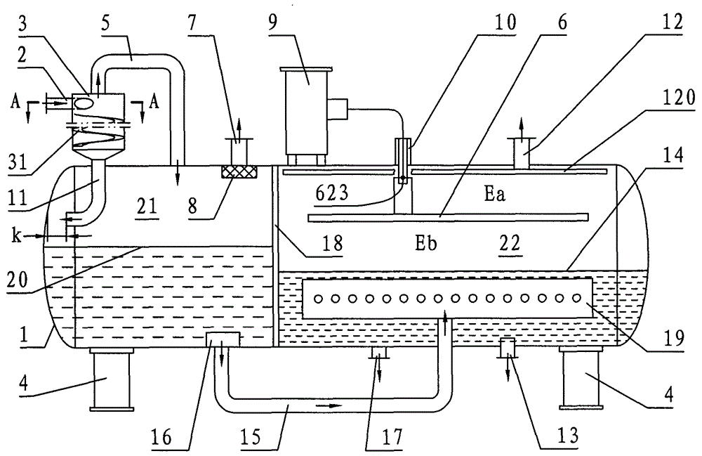
[0014] see figure 1 , A three-phase separator of the present invention is provided with a tank body 1, a cyclone separator 3, an exhaust pipe 7, a transformer 9, and a high-voltage electricity introduction pipe 10. The tank body 1 is a horizontal tank supported by a support 4 . The inner cavity of the tank body 1 is provided with a partition 18 , and the partition plate 18 divides the inner cavity of the tank body 1 into a gas-liquid separation chamber 21 and an oil-water separation chamber 22 . The shell of the cyclone separator 3 is composed of an upper cylindrical shell and a lower inverted truncated conical shell, and a feed pipe 2 is provided along the tangential direction of the cylindrical shell of the cyclone separator 3 . A liquid outlet pipe 11 is provided at the bottom of the cyclone separator 3 , and the outlet of the liquid outlet pipe 11 is located in the gas-liquid separation chamber 21 . An oil outlet pipe 12 is provided at the position of the oil-water separ...


PUM

PropertyMeasurementUnit
widthaaaaaaaaaa
diameteraaaaaaaaaa
thicknessaaaaaaaaaa

Abstract

The invention discloses a three-phase separator which is provided with a tank (1), a cyclone separator (3), a transformer (9), a distributor (19), a plate electrode (6) and the like. The inner cavity of the tank is divided into a gas-liquid separation chamber (21) and an oil-water separation chamber (22) through a separator plate (18). A gas returning pipe (5) is arranged between the top of the cyclone separator and the top of the gas-liquid separation chamber. A spiral plate (31) is arranged on the inner wall of the cylindrical shell of the cyclone separator. The distributor is arranged at the lower part of the oil-water separation chamber, and a liquid conveying pipe (15) is arranged between the lower part of the gas-liquid separation chamber and the distributor. The plate electrode is a single-layer horizontal plate electrode, is arranged on the upper part of the oil-water separation chamber and is composed of a steel wire rope with an insulating layer and several insulating support plates and constant-pitch rods. The three-phase separator provided by the invention is mainly used for three-phase separation of oil, gas and water phases of crude oil produced from oilfields and oil wells.

Description

technical field [0001] The invention belongs to the technical field of oil field surface treatment equipment, and relates to a three-phase separator used for separating oil, gas and water from crude oil produced by oil wells in oil fields. Background technique [0002] Crude oil contains water and natural gas (and sand) after being extracted from oil wells, and it needs to be separated before transportation. The treated purified crude oil and natural gas are exported as products, and the separated water can be used as reinjection water for oil wells. Three-phase separators are generally used for the separation of crude oil produced from oil wells in oil fields, and conventional three-phase separators are separated by gravity sedimentation. However, with the increase of the water content of the produced crude oil, the water content of the crude oil processed by a single conventional three-phase separator is still too high, which affects the subsequent treatment, and even cau...

Claims


Application Information

Patent Timeline
Patent Type & Authority Applications(China)
IPC IPC(8): C10G53/02E21B43/34
Inventor 刘家国崔新安汪实彬袁海欣申明周曹振兴李春贤
Owner LUOYANG PETROCHEMICAL ENG CORP SINOPEC
Why Eureka
Try Eureka