
Electric lifting device for automobile stern door

A lifting device and tailgate technology, which is applied in the field of auto parts, can solve the problems of limited motor power and limited motor outer diameter, and achieve the effects of simplifying structure, increasing power, and reducing production costs

Inactive Publication Date: 2015-11-25
JOHNSON ELECTRIC SHENZHEN
View PDF5 Cites 24 Cited by
  • Summary
  • Abstract
  • Description
  • Claims
  • Application Information

AI Technical Summary

Problems solved by technology

[0003] The disadvantage of this solution is that the housing of the miniature motor is housed in the drive sleeve of limited size, resulting in a very limited outer diameter of the motor, thereby limiting the power of the motor

Method used


Image

  • Electric lifting device for automobile stern door
  • Electric lifting device for automobile stern door
  • Electric lifting device for automobile stern door

Examples


Embodiment Construction

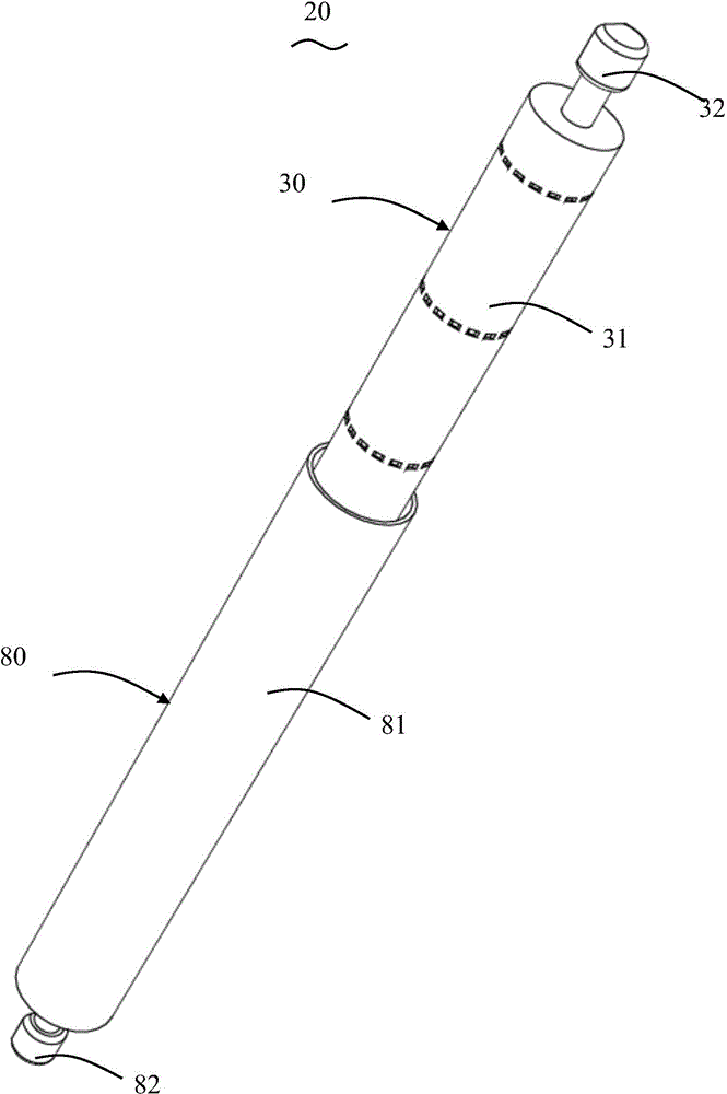
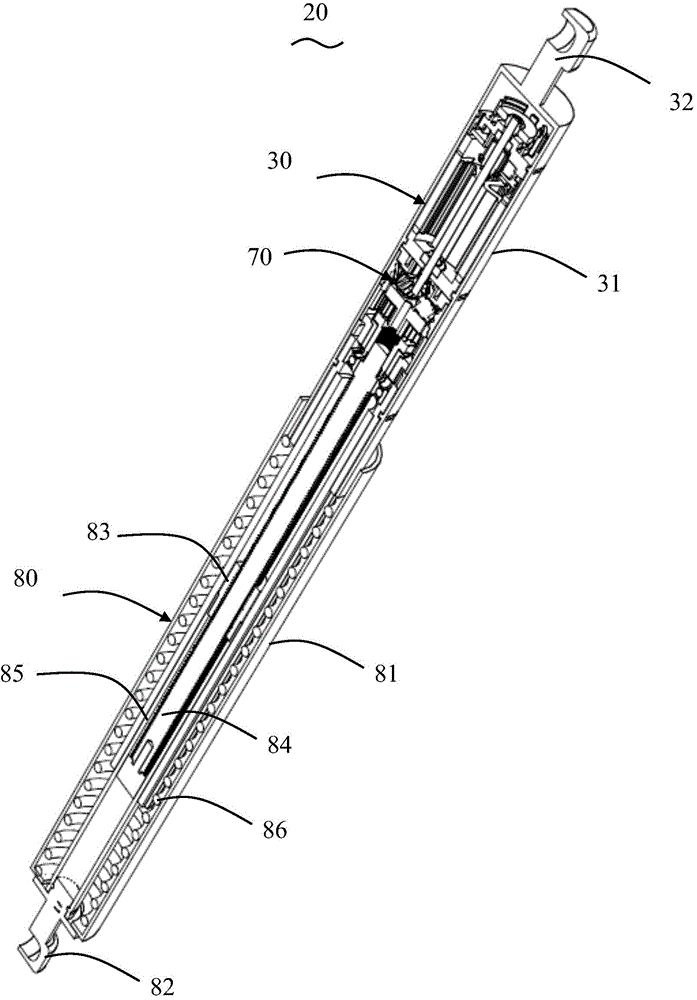
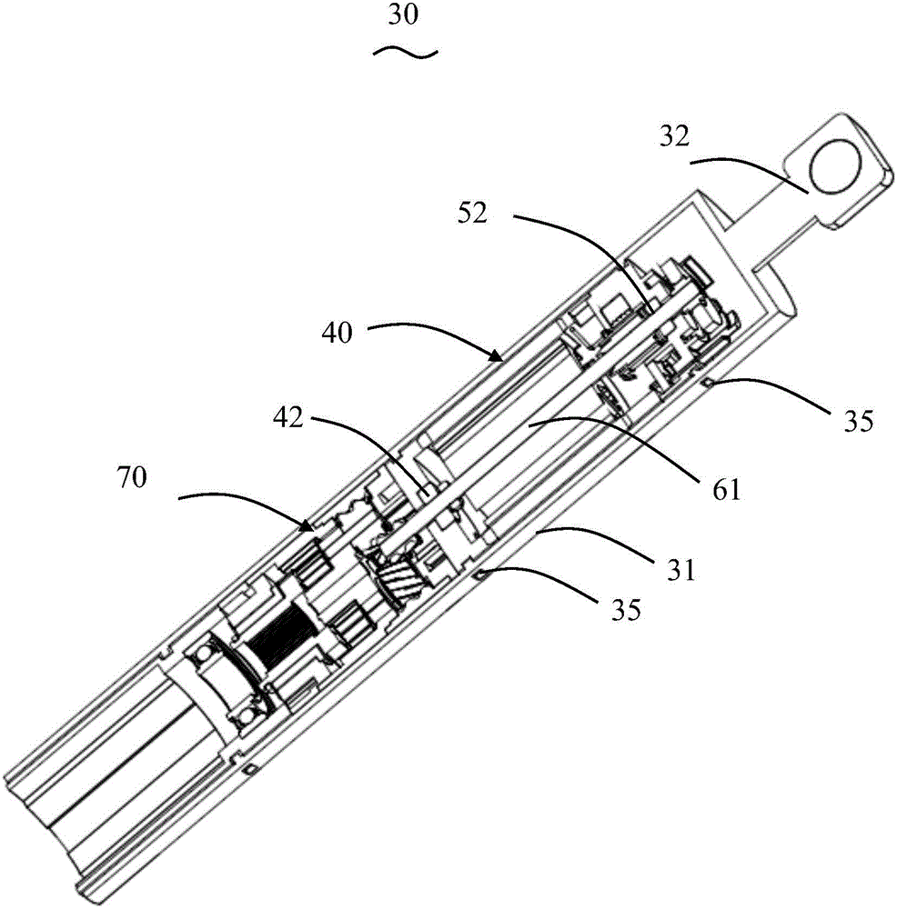
[0025] refer to Figure 1 to Figure 3 According to one embodiment of the present invention, an electric lifting device 20 for a tailgate of an automobile includes a driver 30 and a screw device 80 connected in sequence. The driver 30 includes a driver sleeve 31, a first connector 32 positioned at one end of the driver sleeve 31, a motor assembly 40 installed in the driver sleeve 31, and a gear reduction mechanism 70. The gear reduction mechanism 70 is connected with the motor assembly 40 for deceleration. output. The screw mandrel device 80 comprises a screw mandrel sleeve 81, a second connector 82 positioned at one end of the screw mandrel sleeve 81, a screw mandrel 84 installed in the screw mandrel sleeve 81, a spring 86, etc., the screw mandrel 84 is driven by the gear reduction mechanism 70 Driven, the threads of the screw rod 84 and the nut 83 are used to convert the rotation of the screw rod 84 into the linear motion of the nut 83 . The nut 83 is relatively fixed to th...


PUM


Abstract

A power strut for a vehicle lift gate, has a driver sleeve, a lead screw sleeve, a lead screw and a spring mounted in the lead screw sleeve. A gear reduction mechanism and a motor assembly are mounted in the driver sleeve for driving the lead screw. The motor assembly has a magnet mounting bracket fixed to the driver sleeve and a rotor disposed in the magnet mounting bracket. An end cover and multiple permanent magnets are fixed to the magnet mounting bracket. Each of the magnets is positioned between a corresponding pair of adjacent connecting portions and contacts an inner surface of the driver sleeve, thereby the driver sleeve provides a magnetic path between the magnets.

Description

【Technical field】 [0001] The invention relates to the field of auto parts, in particular to an electric lifting device for an automobile tailgate. 【Background technique】 [0002] More and more cars use electric lifting devices to raise and lower the tailgate of the car. Chinese patent application 201010288083.0 published on February 9, 2011 discloses an electric drive mechanism for an automobile tailgate. The drive mechanism includes a drive sleeve and a screw sleeve, and a micro motor and a planetary gear reducer are installed in the drive sleeve. , A screw and a spring are installed in the screw sleeve. The micromotor includes a stator and a rotor, and the stator includes a casing, a permanent magnet installed on the inner wall of the casing, end covers arranged at both ends of the casing, and the like. The rotor includes a rotating shaft, a rotor core fixed to the rotating shaft, a commutator, etc., and the rotating shaft is supported by bearings provided on end covers ...

Claims


Application Information

Patent Timeline
Patent Type & Authority Applications(China)
IPC IPC(8): E05F15/16H02K7/116
CPCH02K7/06E05F15/622E05Y2900/546H02K1/17H02K1/22H02K5/163H02K5/22H02K7/083H02K7/116H02K7/14H02K13/006H02K13/10
Inventor 张敏佑丹尼斯·格罗斯李学松甘小福熊慧民
Owner JOHNSON ELECTRIC SHENZHEN
Learn More