
fan

A fan and fan blade technology, applied in the field of fans with heat dissipation structure, can solve problems such as shortening the life of motor bearings, and achieve the effects of reducing noise, reducing stagnation area and turbulence, and improving service life

Active Publication Date: 2018-02-09
DELTA ELECTRONICS INC
View PDF4 Cites 0 Cited by
  • Summary
  • Abstract
  • Description
  • Claims
  • Application Information

AI Technical Summary

Problems solved by technology

However, the cooling device of this type of system will generate an ambient temperature of about 70°C, and the temperature of the motor itself that is continuously running at an ambient temperature of 70°C can reach as high as 100°C. This high temperature will greatly reduce the life of the motor bearings

Method used


Image

  • fan
  • fan
  • fan

Examples


Embodiment Construction

[0094] A fan according to a preferred embodiment of the present invention will be described below with reference to related drawings, wherein the same components will be described with the same reference symbols.

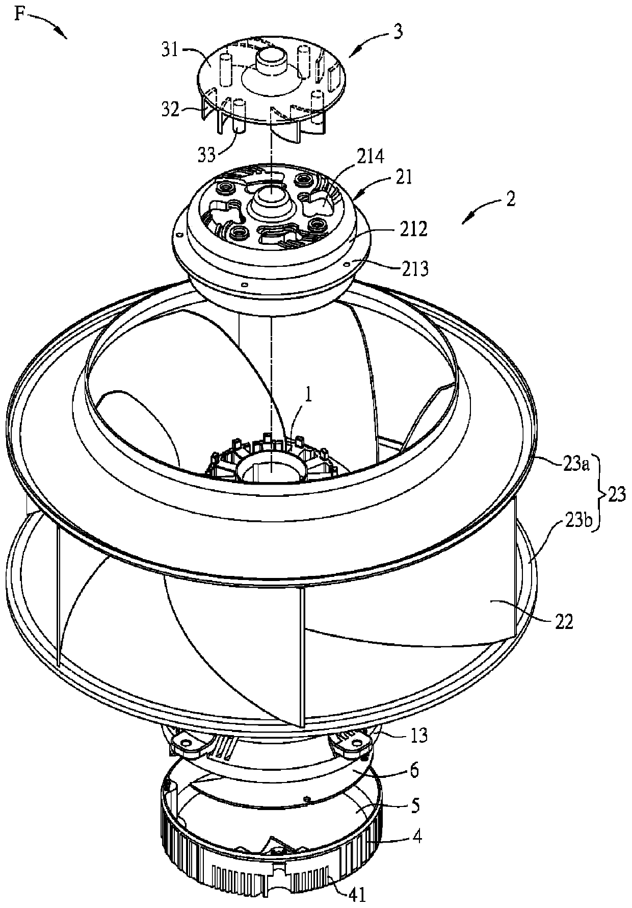
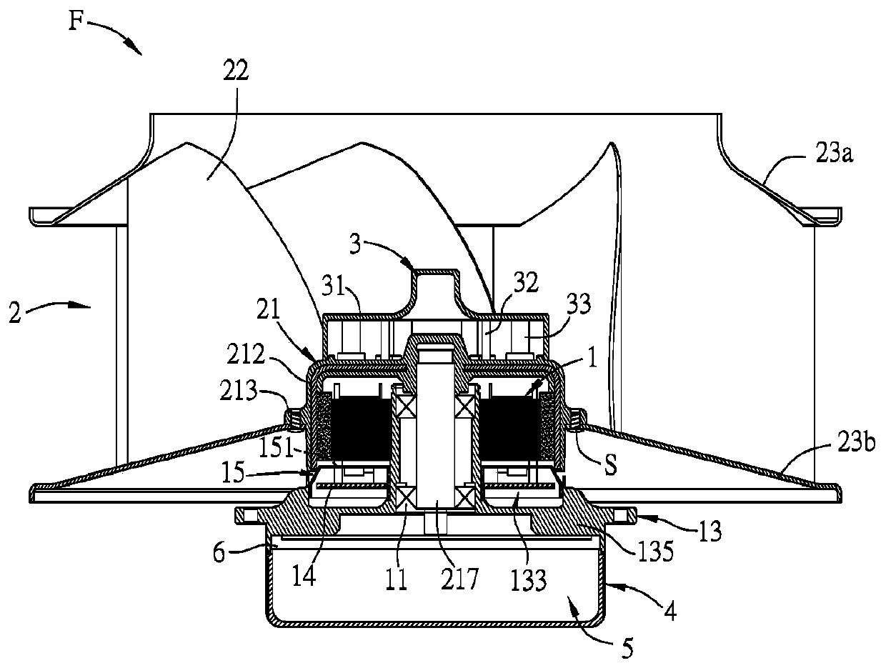
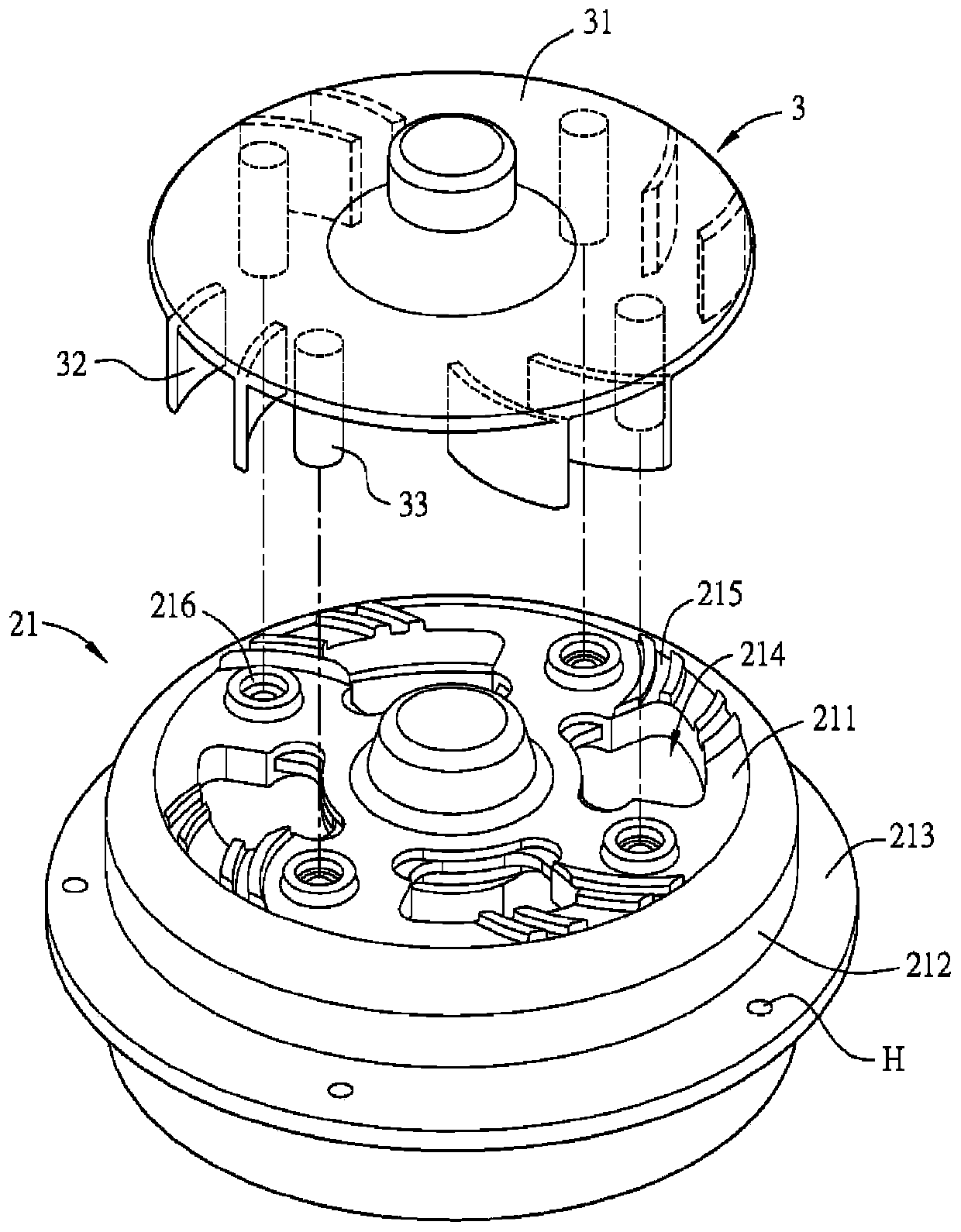
[0095] Figure 1A It is a three-dimensional exploded top view of a fan in a preferred embodiment of the present invention, Figure 1B for Figure 1A Sectional view of the fan shown, please also refer to Figure 1A and Figure 1B shown. The fan F includes a motor 1 , an impeller 2 and a heat dissipation structure 3 . The impeller 2 includes a hub 21 and a plurality of outer fan blades (or first fan blades) 22 . Wherein the hub 21 is a hollow structure, which is used to accommodate the motor 1 and can be divided into a top 211 and a side wall 212 surrounding its outer periphery according to the structure of the hub 21, such as figure 2 shown.

[0096] Please refer to Figure 1A and 1B As shown, the impeller 2 also has two annular structures 23 , and the outer fa...


PUM


Abstract

A fan includes a motor, an impeller and a heat dissipation structure. The motor includes a stator magnetic group, a bearing seat, a first circuit board and a protective cover. The bearing seat carries the stator magnetic group. The bearing base and the stator magnetic assembly form a first accommodating space. The first circuit board is disposed in the first accommodating space. The protective cover covers the first circuit board. The impeller includes a hub and a plurality of first fan blades. The hub is used for accommodating the motor. The hub has at least one cooling hole. The first fan blade is arranged around the hub. The heat dissipation structure is arranged on the outer side of the hub, and has a baffle and at least one second fan blade. The second fan blade extends from the baffle, and the position of the second fan blade corresponds to the cooling hole.

Description

technical field [0001] The invention relates to a fan, in particular to a fan with a heat dissipation structure. Background technique [0002] In the structure of a general fan, the impeller is set on the motor, and the motor provides the power required for the rotation of the impeller to drive the rotation of the impeller, thereby providing sufficient air volume to the heating element to achieve the effect of heat dissipation. Therefore, the current design and manufacturing of fans People in the industry are working hard to design fans that can provide higher air volume. One of the ways to make the fan provide high air volume is to increase the fan speed, however, in the design of the fan, the speed cannot be increased infinitely. Because when the fan rotates at a high speed, its blades will bear extremely high pressure. At this time, the blades will be deformed or even broken, which will cause great danger. [0003] In addition, at high speeds, the mechanism and bearings...

Claims


Application Information

Patent Timeline
Patent Type & Authority Patents(China)
IPC IPC(8): F04D25/08F04D29/58F04D29/28
Inventor 黄诗涵张楯成
Owner DELTA ELECTRONICS INC
Learn More