Heat source machine

A heat source machine and latent heat technology, applied in fluid heaters, lighting and heating equipment, combustion methods, etc., can solve problems such as nozzle hole clogging and gas not coming out

Active Publication Date: 2015-11-25
RINNAI CORP
View PDF11 Cites 4 Cited by
  • Summary
  • Abstract
  • Description
  • Claims
  • Application Information

AI Technical Summary

Problems solved by technology

In this case, although there is no problem with dew condensation at the light nozzle, if it condenses at the thick

Method used


Image

  • Heat source machine
  • Heat source machine
  • Heat source machine

Examples


Embodiment Construction

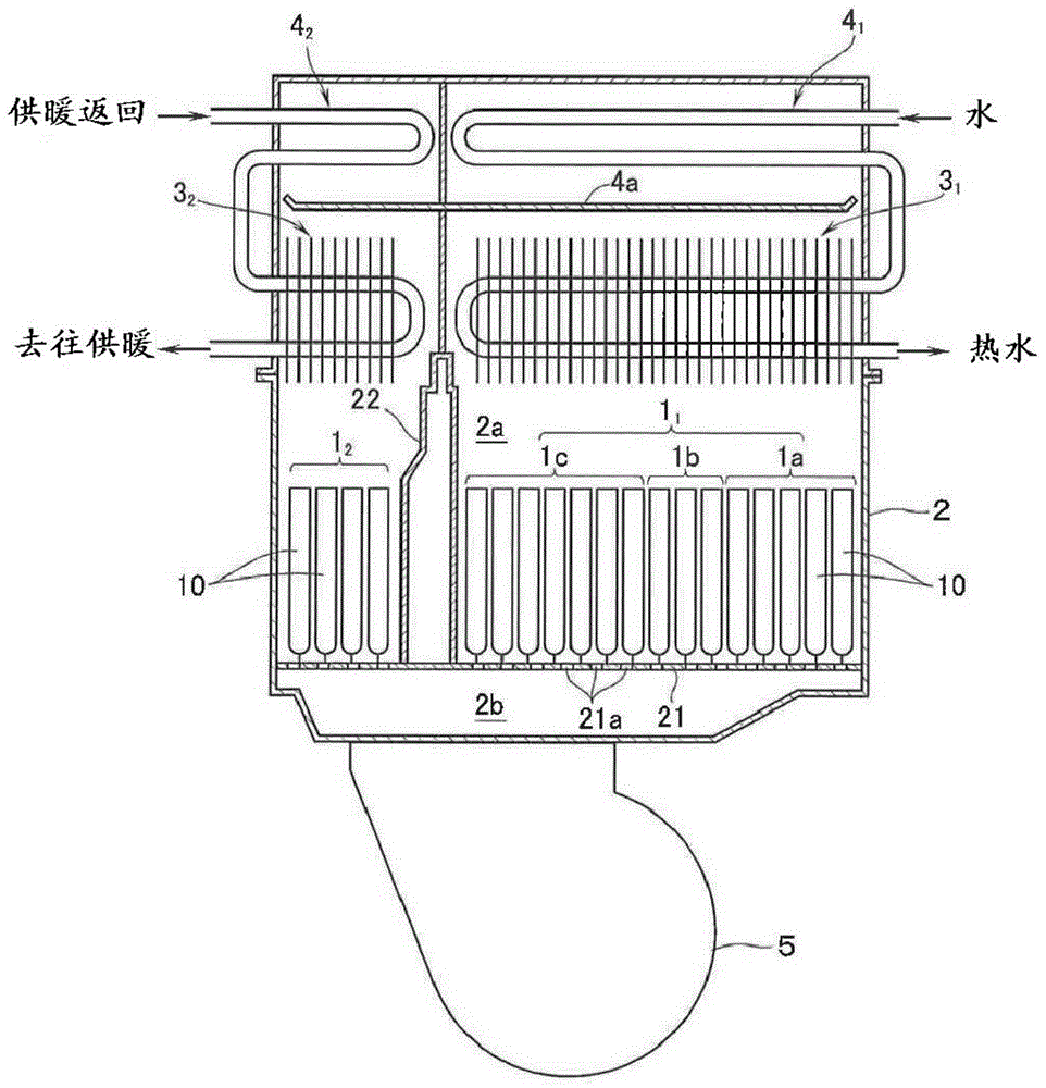
[0017] figure 1 The heat source unit according to the embodiment of the present invention shown is a device for supplying hot water and heating, and the first burner unit 1 for supplying hot water 1 and 2nd burner unit 1 for heating 2 On top of the built-in combustion shell, the 1st burner unit 1 is arranged side by side 1 The first sensible heat recovery type heat exchanger 3 for hot water supply heated by combustion exhaust gas 1 , and using the second burner unit 1 2 The second sensible heat recovery type heat exchanger 3 for heating to heat the combustion exhaust gas 2 , and then, in the first sensible heat recovery heat exchanger 3 1 The first latent heat recovery type heat exchanger 4 for supplying hot water is arranged above 1 , the first latent heat recovery type heat exchanger 4 1 recovery through the 1st sensible heat recovery type heat exchanger 3 1 The latent heat in the combustion exhaust, moreover, in the 2nd sensible heat recovery type heat exchanger 3 2...


PUM


Abstract

The invention provides a heat source machine which comprises sensible heat recycling type and latent heat recycling type heat exchangers. The heat exchangers conduct heating through burner units formed by a plurality of rich lean burners arranged in parallel. Lean spray nozzles (63) facing lean flow inlets of the rich lean burners and rich spray nozzles (64) facing rich flow inlets of the rich lean burners are arranged on gas manifolds (6) used for providing gas for the burner units. Even when operation is stopped and high-humidity air in the latent heat recycling heat exchangers reversely flows and dews at the rich spray nozzles, pour burning caused by spray nozzle hole blockage can not happen. According to the heat source machine, partition walls (68) which partition lean gas chambers (66) used for providing gas for the lean spray nozzles (63) and rich gas chambers (67) used for providing gas for the rich spray nozzles (64) are arranged on the gas manifolds (6). One or more communicating parts (69) used for making each lean gas chamber and the corresponding rich gas chamber communicated is formed on the corresponding partition wall (68). Gas is provided for the rich gas chambers (67) from the lean gas chambers (66) through the communicating parts (69). In addition, the total area of openings of the communicating parts (69) is smaller than the total area of openings of spray nozzle holes of the rich spray nozzles (64).

Description

technical field [0001] The present invention relates to a heat source machine that includes a sensible heat recovery type heat exchanger and a latent heat recovery type heat exchanger, and uses a burner unit formed by arranging a plurality of rich-lean burners in parallel as a means of heating these heat exchangers. The burner unit, the rich-lean burner has a lean flame port and a rich flame port. The lean flame port ejects a lean mixture whose fuel concentration is thinner than the theoretical air-fuel ratio, and the rich flame port ejects a rich mixture whose fuel concentration is richer than the theoretical air-fuel ratio. gas. Background technique [0002] In the past, in this kind of heat source machine, on the gas manifold that provides gas to the burner unit, be provided with the dilute nozzle that is connected to the dilute flow inlet of the dilute flame mouth of each rich-dilute burner to face, and be connected to Rich-lean burners are rich-lean burners with rich-l...

Claims


Application Information

Patent Timeline
IPC IPC(8): F24H9/18F23D14/48F23D14/68
Inventor 清水政一上田庸考
Owner RINNAI CORP
Why Eureka
Try Eureka