Inverse substructure technology-based transmission path analysis method

A transfer path analysis and inverse substructure technology, applied in the field of vibration and noise transfer path analysis, can solve problems affecting the accuracy of contribution

Inactive Publication Date: 2015-11-25
SOUTH CHINA UNIV OF TECH
View PDF6 Cites 14 Cited by
  • Summary
  • Abstract
  • Description
  • Claims
  • Application Information

AI Technical Summary

Problems solved by technology

The actual test requires special test equipment, and the test results are affected by factors such as equipment accuracy,

Method used


Image

  • Inverse substructure technology-based transmission path analysis method
  • Inverse substructure technology-based transmission path analysis method
  • Inverse substructure technology-based transmission path analysis method

Examples


Embodiment

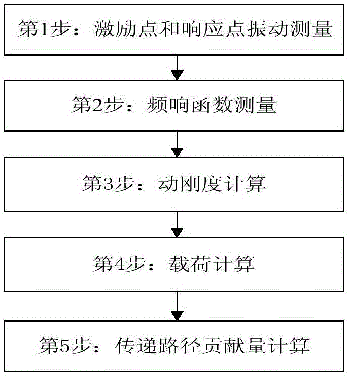
[0037] Such as figure 1 As shown, it is the process flow of the inverse substructure transmission path analysis method of the present invention; when conducting the transmission path analysis test, firstly, the vehicle is run in the set working condition, and the vibration signals of the selected excitation points and target points are measured. Then, according to the needs, the frequency response function of the whole vehicle system level is measured. The third step is to calculate the dynamic stiffness according to formula (3). In the fourth step, the dynamic stiffness is obtained, and the load can be calculated according to formula (4). Finally, the transmission path contribution can be calculated according to formula (1).

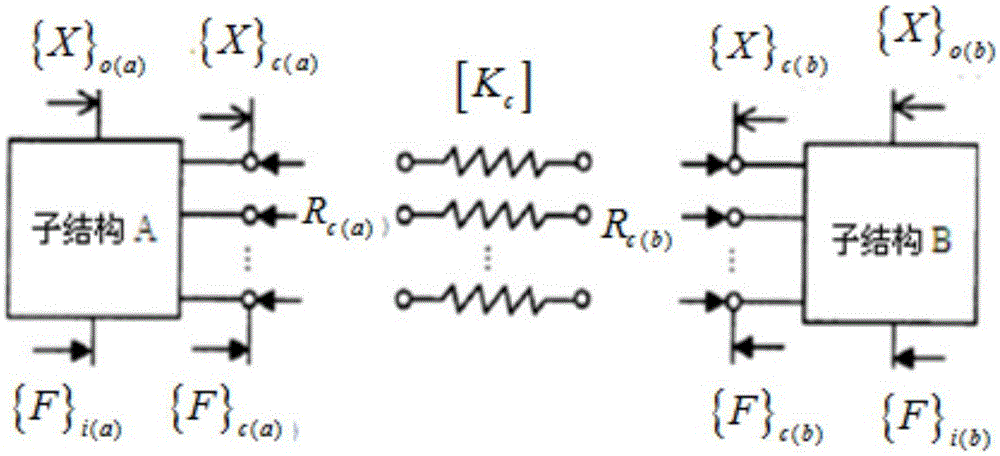
[0038] Calculate the suspension dynamic stiffness in the following way. A system is decomposed into substructure A and substructure B, and the two substructures are coupled at multiple points through elastic elements, such as engine mounts, such as ...


PUM


Abstract

The invention discloses an inverse substructure technology-based transmission path analysis method. The method comprises the steps of 1, sensing and acquiring an excitation signal and a response signal; 2, sensing and acquiring a frequency response function; 3, calculating the dynamic stiffness; 4, calculating the load; 5, calculating the contribution of a transmission path. The method overcomes the defect in the prior art that the test result of dedicated equipment is different from the state of a real vehicle. Therefore, the obtained contribution of the transmission path is enabled to be much closer to the real state of the overall vehicle.

Description

technical field [0001] The invention relates to a vibration and noise transmission path analysis technology, in particular to a transmission path analysis method based on inverse substructure technology. Background technique [0002] Vehicles, especially hybrid vehicles, have many vibration sources, such as road excitation, tire excitation, engine excitation, motor excitation, exhaust system excitation, etc. These vibration sources have an impact on the vibration and noise in the car, etc. Judging these vibration sources The contribution of vibration and noise to the target point is the premise of vibration and noise reduction. At present, the transfer path analysis methods commonly used to analyze the contribution of vibration sources mainly include the traditional transfer path analysis method and the working condition transfer path analysis method, and most other methods are improved based on these two methods. The traditional transfer path analysis method has high preci...

Claims


Application Information

Patent Timeline
IPC IPC(8): G01M7/02G01M5/00G01M17/007G01M17/04
Inventor 陈吉清莫愁兰凤崇
Owner SOUTH CHINA UNIV OF TECH
Why Eureka
Try Eureka