
A friction test device and test method for screw drilling tool rotor coating

A screw drilling tool and test device technology, which is applied in the direction of testing wear resistance, etc., can solve the problem of not being able to provide accurate data support for the research on the wear resistance of the rotor coating, not being able to simulate the screw drilling tool rotor well, and being unfavorable for researching the screw drilling tool and other problems, to achieve the effect of small footprint, acceptable test data, and small volume

Active Publication Date: 2017-12-01
DEZHOU UNITED GASOLINEEUM MACHINERY
View PDF4 Cites 113 Cited by
  • Summary
  • Abstract
  • Description
  • Claims
  • Application Information

AI Technical Summary

Problems solved by technology

[0002] Some of the current test devices used to detect the friction performance of the coating cannot simulate the actual working conditions of the screw drill rotor well. Therefore, when used to detect the coating of the screw drill rotor, it cannot better reflect the The friction conditions in actual working conditions, the data obtained from the test are often quite different from the actual work, and cannot provide accurate data support for the research on the wear resistance of the rotor coating, which is not conducive to better research and further improvement of the screw drilling tool rotor length. life demand performance

Method used


Image

  • A friction test device and test method for screw drilling tool rotor coating
  • A friction test device and test method for screw drilling tool rotor coating
  • A friction test device and test method for screw drilling tool rotor coating

Examples


Embodiment Construction

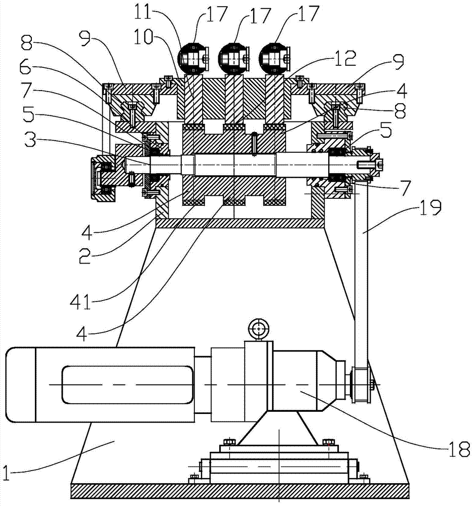
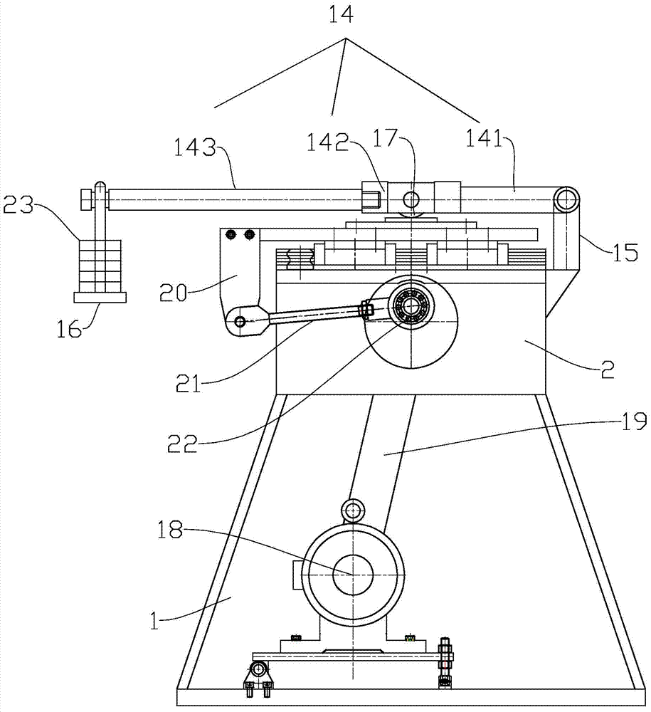
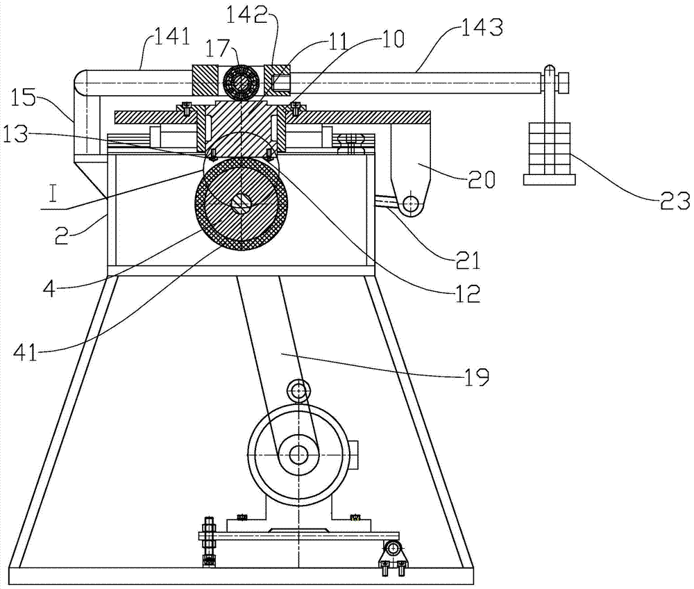
[0048] Such as figure 1 , 2 , 3, the screw drilling tool rotor coating friction test device mainly includes a frame, a box body, a grinding wheel assembly, a line rail assembly, a linear motion assembly, a pressurized assembly, a reducer with a motor, and a linear motion assembly drive mechanism .

[0049] The box body 2 is fixedly arranged on the frame 1. The box is used to hold mud liquid.

[0050] The grinding wheel assembly includes a main shaft 3 and a grinding wheel 4 . Both ends of the main shaft 3 pass through the left and right sides of the box body 2 and are supported by bearings 5 ​​. The casing 2 is provided with an end cover 6 at the position where the main shaft 3 passes, and a sealing ring 7 is provided between the end cover 6 and the main shaft 3 to prevent the mud liquid from leaking and entering the bearing, causing damage to the bearing. There are multiple grinding wheels, and the grinding wheels 4 are equal in diameter and fixed on the main shaft 3 . ...


PUM


Abstract

The invention discloses a screw rd drilling tool rotor cladding layer friction test device and a screw rod drilling tool rotor cladding layer friction test method. The device comprises a rack, a box, a grinding wheel assembly, a linear rail assembly, a rectilinear motion assembly, a pressurizing assembly, a speed reducing machine with a motor, and a rectilinear motion assembly driving mechanism. Mud liquid is added in the box; a main shaft of the grinding wheel assembly penetrates through the box; a plurality of grinding wheels are fixedly arranged on the main shaft; at least lower parts of the grinding wheels are positioned in the box; two linear rails of the linear rail assembly are fixed at two sides of the box and are vertical to the main shaft; a base part of the rectilinear motion assembly runs on the linear rails; a pressing block limiting device is arranged on the base part; pressing blocks in the pressurizing assembly are arranged in pressing block installation holes in the pressing block limiting device; the bottom surface of each pressing block clamps a test piece; each pressing block is loaded by a lever mechanism and a pressure applying roller; the speed reducing machine drives the main shaft to rotate by a belt transmission mechanism; the main shaft rotates to drive the rectilinear motion assembly to run by a cam mechanism and a connection rod. Test data are relatively desirable, so that a relatively accurate data support is provided for study on a wear-resisting property of a cladding layer.

Description

technical field [0001] The invention relates to a friction test device and a test method for a screw drilling tool rotor coating. Background technique [0002] Some of the current test devices used to detect the friction performance of the coating cannot simulate the actual working conditions of the screw drill rotor well. Therefore, when used to detect the coating of the screw drill rotor, it cannot better reflect the The friction conditions in actual working conditions, the data obtained from the test are often quite different from the actual work, and cannot provide accurate data support for the research on the wear resistance of the rotor coating, which is not conducive to better research and further improvement of the screw drilling tool rotor length. Longevity demand performance. Therefore, it is necessary to develop a dedicated screw drilling tool rotor coating friction test device and test method to improve the accuracy of the data. Contents of the invention [0...

Claims


Application Information

Patent Timeline
Patent Type & Authority Patents(China)
IPC IPC(8): G01N3/56
Inventor 殷凤玲于卫东赵振华于广海裴洪军白广辽
Owner DEZHOU UNITED GASOLINEEUM MACHINERY
Learn More