Power system power factor measurement device, method and system

A power factor, power system technology, applied in the direction of electric power measurement through current/voltage, etc., can solve problems such as large current, damage to low-voltage circuit breakers, and inability to measure the power factor of short-circuit test systems

Active Publication Date: 2018-02-02
SUZHOU SIEMENS ELECTRIC APPLIANCE
View PDF8 Cites 1 Cited by
  • Summary
  • Abstract
  • Description
  • Claims
  • Application Information

AI Technical Summary

Problems solved by technology

However, the current for testing low-voltage and high-current test samples will be very large, usually above 65kA (even above 120kA), that is to say, the current value of the low-voltage side (secondary side) of the transformer is very large, and the secondary side of the transformer The protective switch (low-voltage circuit breaker) cannot withstand the arc generated by such a large current during the on-off process, and it is easy to damage the low-voltage circuit breaker. Therefore, the phase angle difference method cannot simultaneously measure the voltage signal and current signal of low-voltage and high-current , making it impossible to measure the power factor of the short-circuit test system during short-circuit

Method used


Image

  • Power system power factor measurement device, method and system
  • Power system power factor measurement device, method and system
  • Power system power factor measurement device, method and system

Examples


Embodiment Construction

[0042] In order to have a clearer understanding of the technical features, purposes and effects of the present invention, the specific implementation manners of the present invention will now be described with reference to the accompanying drawings.

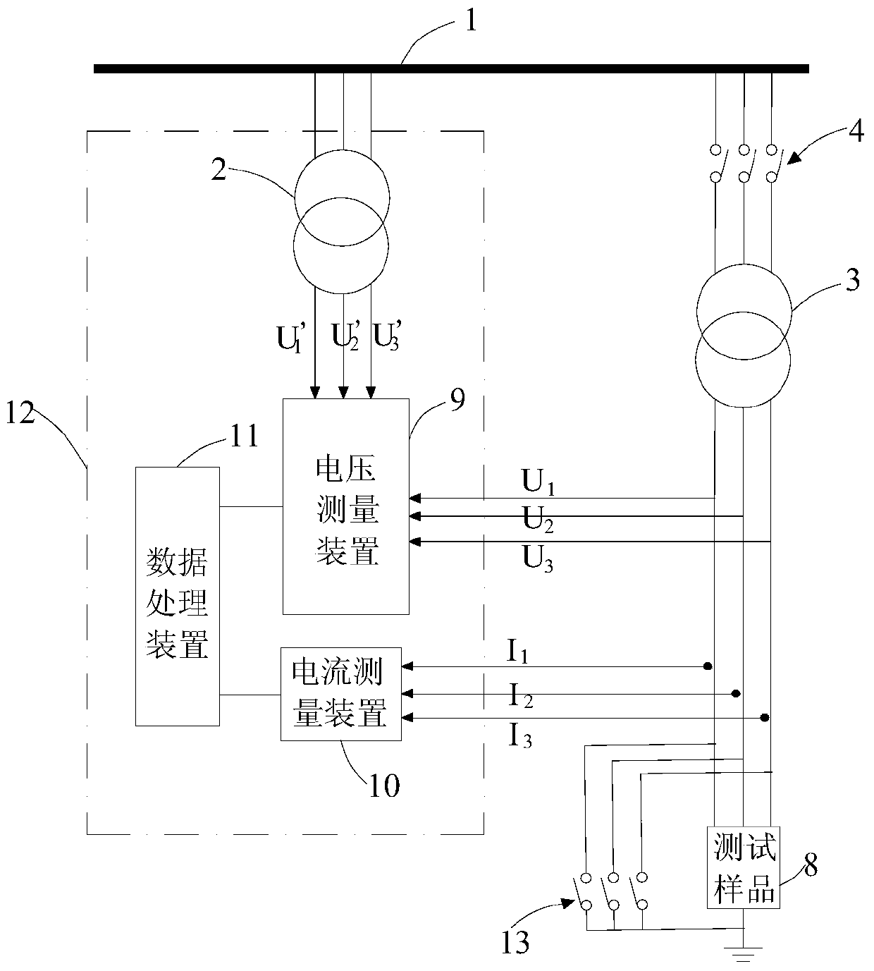
[0043] figure 1 It is a schematic diagram of the circuit structure of the short-circuit test system of the first embodiment of the present invention. Such as figure 1 As shown, the power system includes a power supply line 1, a protection switch 4, a short-circuit switch 13, and a power transformer 3. The power supply line 1 is a power line that provides three-phase alternating current, and the primary side of the power transformer 3 is connected to the power supply line 1 through the protection switch 4. On the secondary side of the power transformer 3, a short-circuit switch 13 is also connected. The power factor measuring device 12 of this embodiment includes a voltage transformer 2 , a voltage measuring device 9 , a current...


PUM


Abstract

The invention provides a power factor measuring device, a measuring method and a short-circuit test system thereof for a power system. The power system includes a power supply line, a protection switch, a power transformer and a short-circuit switch. The power factor measuring device includes: a voltage transformer, a voltage transformer The primary side of the transformer is connected to the power supply line; the voltage measurement device is used to simultaneously obtain the first voltage waveform of the secondary side of the voltage transformer and the voltage of the power transformer when the protection switch is in the closed state and the short-circuit switch is in the open state The second voltage waveform of the secondary side; the current measuring device is used to obtain the current waveform of the secondary side of the power transformer when the protection switch is in the closed state and the short-circuit switch is in the closed state, and the voltage measuring device obtains the second voltage waveform of the voltage transformer The third voltage waveform of the secondary side; the data processing device is used to calculate the power factor. According to the invention, the power factor when the power system is short-circuited can be more accurately measured.

Description

technical field [0001] The invention relates to the field of power electronics, in particular to a power factor measuring device, a measuring method and a test system thereof. Background technique [0002] With the increase of power load and the improvement of power quality, the safety requirements for low-voltage and high-current switchgear are getting higher and higher. Therefore, it is necessary to carry out factory inspection and type test for complete sets of switchgear such as circuit breakers and switchgear. In the low-voltage and high-current short-circuit test system, in addition to providing the test voltage and test current required by the sample test, the power factor provided by the short-circuit test system must also meet the requirements, so it is necessary to accurately measure and calculate the short-circuit test system. Power factor, that is, power factor angle. [0003] At present, the methods for calculating the power factor in the short-circuit test sys...

Claims


Application Information

Patent Timeline
Patent Type & Authority Patents(China)
IPC IPC(8): G01R21/06
Inventor 杨祥蒋凡海因里希·维斯梅特马库斯·克尔纳斯文·魏冈
Owner SUZHOU SIEMENS ELECTRIC APPLIANCE
Why Eureka
Try Eureka