Automatic chip power-on reliability detection device and detection method

An automatic detection device and reliability technology, applied in the direction of electronic circuit testing, etc., can solve problems such as errors, unsuitability, and inaccurate measurement

Active Publication Date: 2015-11-25
NAT UNIV OF DEFENSE TECH
View PDF7 Cites 33 Cited by
  • Summary
  • Abstract
  • Description
  • Claims
  • Application Information

AI Technical Summary

Problems solved by technology

[0006] The technical problem to be solved by the present invention is: Aiming at the technical problems existing in the prior art that manual operation is easy to cause mistakes, measurement is inaccurate, and it is not suitable f

Method used


Image

  • Automatic chip power-on reliability detection device and detection method
  • Automatic chip power-on reliability detection device and detection method
  • Automatic chip power-on reliability detection device and detection method

Examples


Embodiment Construction

[0073] The present invention will be further described in detail below in conjunction with the accompanying drawings and specific embodiments.

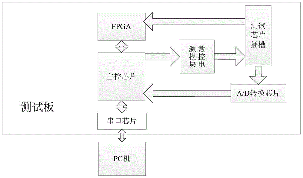
[0074] Such as figure 1 As shown, the present invention provides an automatic detection device for chip power-on reliability, including a PC for running test software and a test board for chip testing. The PC is connected with the test board through a serial port cable and communicates.

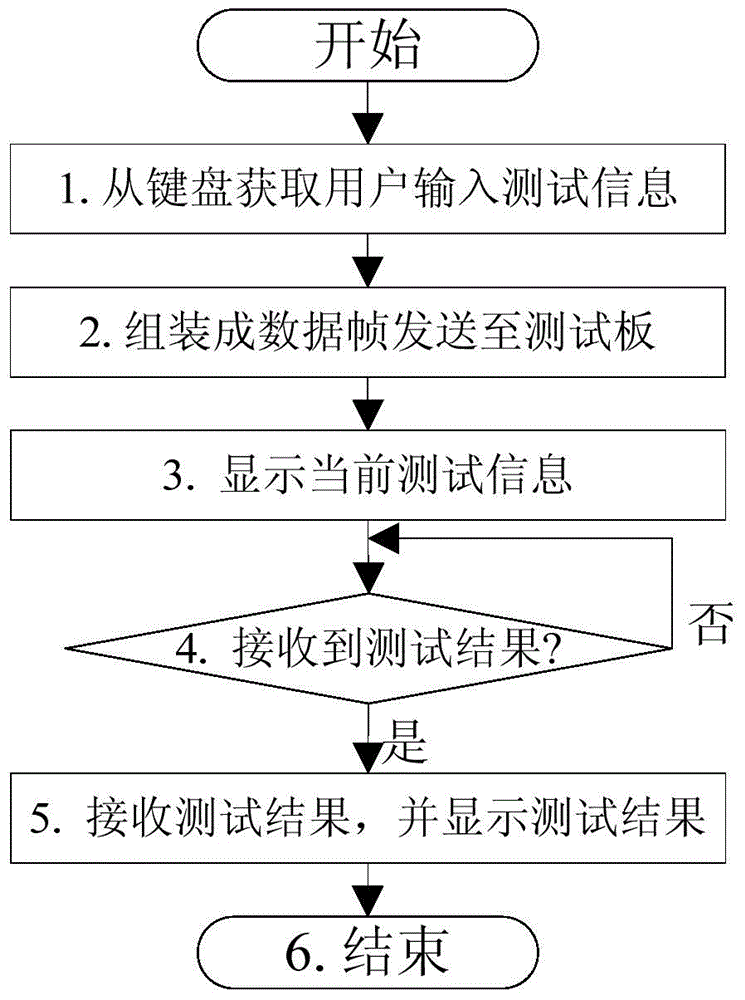
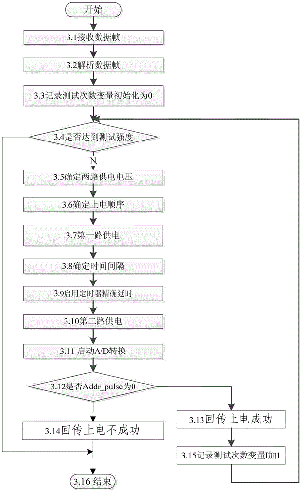
[0075] The test software is installed in the PC, and the test software receives the chip type, test intensity (that is, the number of repeated power-on times), power-on sequence (core power supply first, then I / O power supply, or vice versa) and power-on voltage value input by the tester. And the control information of the time interval (that is, the time difference between power-on of the core and I / O, in order to avoid damage to the chip caused by too long interval, the time difference is limited to 1s by software judgment), and the test software ...


PUM


Abstract

The invention discloses an automatic chip power-on reliability detection device and a detection method and aims to solve technical problems in the prior art that hand-operated operation easily causes errors, measurement is inaccurate, and long-time and large-intensity power-on detection is not suitable. The device comprises a PC used for operating display and control software and a test board for chip tests, wherein the PC is equipped with the display and control software, and the test board comprises a serial port chip, an FPGA, a main control chip, a numerical control power supply module, an A/D conversion chip, a slot of a test chip and a card in matching with the slot of the test chip. The automatic chip power-on detection method comprises steps that, the PC receives test information, the display and control software assembles the test information into data frames and sends the data frames to the serial port chip, a tested chip is tested through the test board, and the data frames transferred from the FPGA are parsed by the automatic power-on reliability detection software of the main control chip. According to the device and the method, test result accuracy is improved, the test process is simple, and operation is simple and convenient.

Description

technical field [0001] The invention relates to the technical field of chip automatic detection, in particular to a chip power-on reliability detection device and detection method. Background technique [0002] The chip is composed of an external I / O circuit (hereinafter referred to as the I / O circuit) and a core circuit. The core circuit is the core operation part inside the chip. It is composed of an operation unit, a register file, a cache and a conventional storage unit. The data is processed at high speed and output to the outside of the chip through the I / O circuit. The I / O circuit is the bridge connecting the core of the chip and the external pins. It is mainly distributed on the periphery of the chip and has functions such as logic input and output, level conversion, and chip protection. Typical ESD (Electro-Static Discharge, electrostatic discharge) protection circuit, power-on sequence control protection circuit, etc. The I / O circuit and the core circuit of the c...

Claims


Application Information

Patent Timeline
IPC IPC(8): G01R31/28
Inventor 陈跃跃扈啸郝成龙粟毅张世亮吴家铸龚国辉孙海燕刘仲阳柳王霁
Owner NAT UNIV OF DEFENSE TECH
Why Eureka
Try Eureka