
Patsnap Eureka
For R&D, Patsnap Eureka makes reading and utilizing patents & technical documents easy.
Patsnap Eureka AIR
Designed for self-driven R&D workflows. Generate viable solutions, solve complex R&D challenges, empower your innovation with AI.

Patsnap Eureka Materials
Designed for material experts only. Revolutionize your material R&D, from search, analyze, to developing new materials.

TechResearch
Generate reliable direction feasibility study reports for your R&D in just a few steps.

TechSeek
Discover and master advanced knowledge NOW. Basics, ideas, possibilities, all at once.

TechMind
As an expert in R&D Theories, TechMind can generates customized viable solutions instantly.

TechRisk
Analyze your overall solution with one click, know your potential R&D risks in advance.

TechMonitor
Get weekly tech updates, stay abreast of the latest tech innovations and key insights.
Magnetic field detection sensor and magnetic field detection device using same
A technology for detecting sensors and magnetic fields, applied in measurement devices, instruments, measuring magnetic variables, etc., can solve the problems of reducing manufacturing costs and miniaturizing sensors, and achieve the effect of reducing manufacturing costs and suppressing product costs.
- Summary
- Abstract
- Description
- Claims
- Application Information
AI Technical Summary
Problems solved by technology
Method used
Image

Examples
Embodiment approach 1
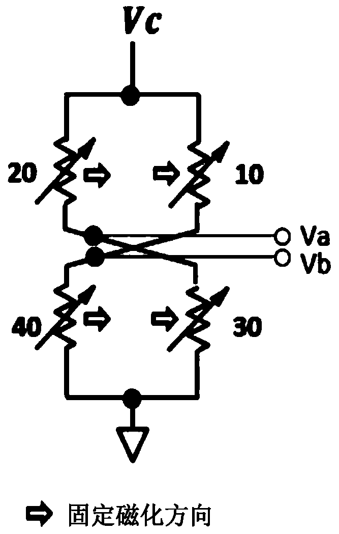
[0045] figure 1 It is a schematic diagram of a bridge circuit constituting the magnetic field detection sensor according to the first embodiment. The bridge circuit includes a first magnetoresistance effect element 10 , a second magnetoresistance effect element 20 , a third magnetoresistance effect element 30 , and a fourth magnetoresistance effect element 40 . The fixed magnetization directions of the first to fourth magnetoresistance effect elements (10, 20, 30, 40) are the same. One end of the first magnetoresistance effect element 10 and one end of the second magnetoresistance effect element 20 are connected to the power supply terminal Vc. The other end of the first magnetoresistance effect element 10 is connected to one end of the fourth magnetoresistance effect element 40 , and the other end of the second magnetoresistance effect element 20 is connected to one end of the third magnetoresistance effect element 30 . The other end of the third magnetoresistance effect el...
Embodiment approach 2
[0062] Figure 7 and Figure 8 It is a biological field measurement device which is an example of a magnetic field detection device using the above-mentioned magnetic field detection sensor according to the second embodiment. Since one or more of the above-mentioned magnetic field detection sensors are arranged in contact with the detected part and each output is a minute signal, a lock-in amplifier circuit or the like is used in the measuring part to perform measurement. In addition, in order to remove irregular repetitive signals such as an external magnetic field or a spontaneous magnetic field, an analog filter such as a band-pass filter or digital processing such as an arithmetic mean method may be used as appropriate.
[0063] Explanation of symbols
[0064] 1 stack
[0065] 10, 20, 30, 40, 50, 60 magnetoresistance effect element
[0066] 100 Magnetic Field Generating Conductors
[0067] 200, 210 Terminal pads
[0068] 300 sense resistor
[0069] 400 differential ...
PUM
 Abstract
Description
Claims
Application Information
 - R&D Engineer
- R&D Manager
- IP Professional
- Industry Leading Data Capabilities
- Powerful AI technology
- Patent DNA Extraction
Browse by: Latest US Patents, China's latest patents, Technical Efficacy Thesaurus, Application Domain, Technology Topic, Popular Technical Reports.
© 2024 PatSnap. All rights reserved.Legal|Privacy policy|Modern Slavery Act Transparency Statement|Sitemap|About US| Contact US: help@patsnap.com