
Display panel and display device

A technology for display panels and array substrates, applied in instruments, nonlinear optics, optics, etc., can solve problems such as difficult control, high manufacturing cost of color filter substrates, stability, and small margin of process difficulty, and achieves simplified production process, The effect of saving production costs and saving production time

Inactive Publication Date: 2015-11-25
BOE TECH GRP CO LTD +1
View PDF0 Cites 1 Cited by
  • Summary
  • Abstract
  • Description
  • Claims
  • Application Information

AI Technical Summary

Problems solved by technology

[0003] The manufacturing process of the above-mentioned color filter substrate in the prior art is relatively complicated and has a small margin of stability and process difficulty, which is difficult to control; resulting in high manufacturing cost of the color filter substrate and the need to consume more labor costs
During the use of the display device, the RGB basic color units of the color filter substrate filter the incident white light, so that the incident light intensity attenuates. As the use time increases, the color of the RGB basic color units of the color filter substrate will gradually decay. Affect the display effect

Method used


Image

  • Display panel and display device
  • Display panel and display device
  • Display panel and display device

Examples


Embodiment Construction

[0024] In order to make the technical problems, technical solutions and advantages to be solved by the present invention clearer, the following will describe in detail with reference to the drawings and specific embodiments.

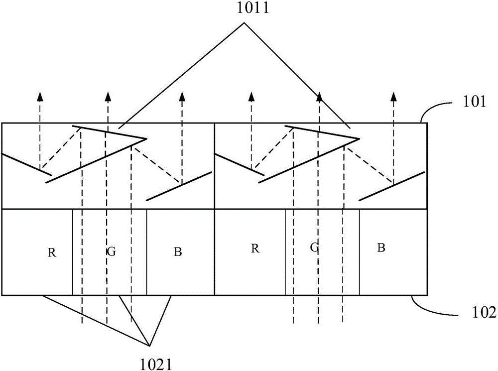
[0025] The present invention firstly provides a display panel with a structure such as figure 1 shown, including:

[0026] The array substrate 102, the color filter layer 101 located on the light-emitting side of the array substrate; the color filter layer 101 includes a plurality of micromirror units 1011 corresponding to each pixel unit 1021 on the array substrate 102, and one pixel unit includes three The sub-pixel unit 1021 ; the micromirror unit 1011 is used to filter and separate the white light passing through the array substrate 102 to obtain three primary color lights corresponding to the three sub-pixels 1021 .

[0027] In the present invention, the color filter layer is used to replace the color film substrate used to generate monochromatic l...


PUM


Abstract

The invention provides a display panel and a display device. The display panel comprises an array substrate and a color filter layer located on the light emitting side of the array substrate; the color filter layer comprises multiple micromirror units which are in one-to-one correspondence with pixel units in the array substrate, and each pixel unit comprises three sub pixel units; the micromirror units are used for conducting filtration and separation on white light passing through the array substrate, and light with three primary colors in one-to-one correspondence with three sub pixels is obtained.

Description

technical field [0001] The invention relates to the field of liquid crystal display, in particular to a display panel and a display device. Background technique [0002] In the semiconductor industry, the display effect is achieved by combining the TFT-ARRAY array with the color film layer and the liquid crystal layer. The color film layer is composed of different ITO formed Red (red light) units, Green (green light) units, Blue (blue light) ) unit (red, green and blue color filter) unit, respectively used to filter out red, green and blue from incident white light; in addition to red light unit, green light unit, blue light unit, also includes BM (BlackMatrix, black matrix ), used to isolate the red light unit, filter unit, and blue light unit respectively. In the color film technology, by forming BM on a layer of substrate as the dividing line of R (Red, red light) G (Green, green light) B (Blue, blue light) basic color pixel unit, three different colors of red, green and...

Claims


Application Information

Patent Timeline
IPC IPC(8): G02F1/1335G02F1/13357
CPCG02F1/1335G02F1/133514G02F1/133553G02F1/1336G02F1/136209
Inventor 周庆高孟盼盼冯忠李鹏杨子衡吴代吾侯智
Owner BOE TECH GRP CO LTD
Learn More