
Touch panel

A touch panel and substrate technology, applied in the field of touch technology, can solve the problems of aging, opacity, decline, and damage to the appearance of the touch panel, etc.

Active Publication Date: 2015-11-25
TPK TOUCH SOLUTIONS (XIAMEN) INC
View PDF4 Cites 5 Cited by
  • Summary
  • Abstract
  • Description
  • Claims
  • Application Information

AI Technical Summary

Problems solved by technology

[0004] However, the manufacturing process of the touch panel includes the process of anti-ultraviolet light testing, and the touch panel may be exposed to sunlight for a long time during use. Due to the influence of ultraviolet light (mainly in the wavelength range of 280nm to 420nm), the shielding layer will be damaged. Aging causes opacity to decrease, which seriously damages the appearance of the touch panel; therefore, the industry needs a touch panel with anti-ultraviolet light ability and prevents the opacity of the non-visible area from decreasing.

Method used


Image

  • Touch panel
  • Touch panel
  • Touch panel

Examples


Embodiment Construction

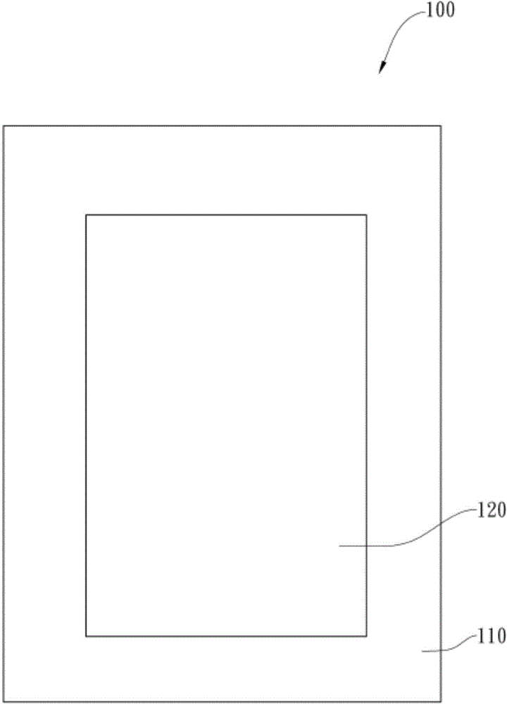
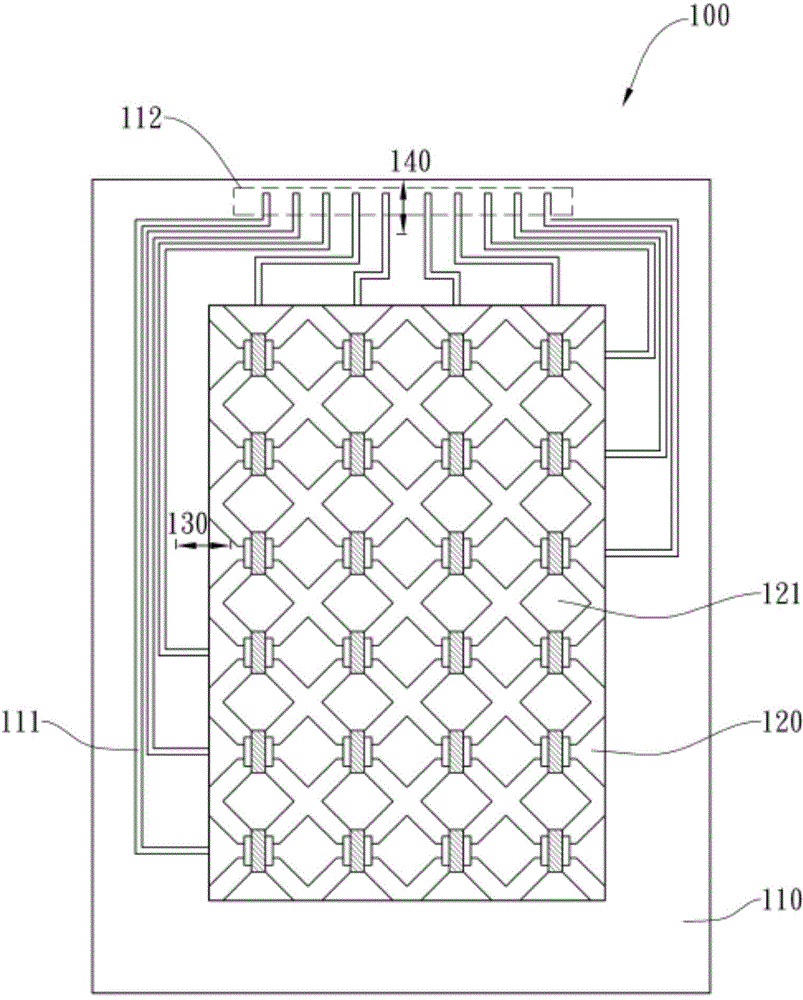
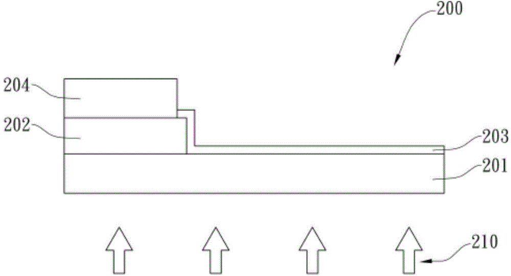
[0015] Although the present invention will be fully described with reference to the accompanying drawings, which contain preferred embodiments of the present invention, it should be understood that those skilled in the art can modify the invention described herein while obtaining the efficacy of the present invention before proceeding to the description. Therefore, it should be understood that the following description is a broad disclosure for those skilled in the art, and its content is not intended to limit the present invention. For example, the statement that the second component is disposed on one side of the first component may include an embodiment in which the first component is in direct contact with the second component, and also includes an embodiment in which an additional component is formed between the first component and the second component, An embodiment in which the first component is not in direct contact with the second component. In addition, the orientat...


PUM

PropertyMeasurementUnit
Thicknessaaaaaaaaaa
Thicknessaaaaaaaaaa
Viscosityaaaaaaaaaa

Abstract

A touch panel with a viewable region and a non-viewable region defined regarding thereto is provided. The touch panel includes: a shielding layer disposed on one side of a substrate, wherein the shielding layer defines the non-viewable region; a sensing electrode layer disposed on the same side as the shielding layer regarding the substrate, wherein at least part of the sensing electrode layer is disposed on the surface of the substrate and is disposed at least within the viewable region; a signal trace layer disposed on the opposing side of the shielding layer with respect to the substrate, and the signal trace layer electrically connected to the sensor electrode layer, wherein the signal trace layer comprises a plurality of metal traces; and an anti-yellowing layer, the anti-yellowing layer being disposed on the opposing side of the substrate with respect to the shielding layer, or the anti-yellowing layer being disposed between the substrate and the shielding layer.

Description

technical field [0001] The present invention relates to a touch technology, and in particular to a touch panel. Background technique [0002] With the evolution of touch technology (Touchcontrol), touch panels (touchpanel) have been widely used in various consumer electronic devices, such as: smart phones, tablet computers, cameras, e-books, MP3 players and other portable electronic products, Or the display screen applied to the operation control equipment. [0003] A touch panel is usually defined with a non-visible area and a visible area corresponding to the non-visible area. Defined by the placement of a masking layer, the material of which is usually ink or photoresist. [0004] However, the manufacturing process of the touch panel includes the process of anti-ultraviolet light testing, and the touch panel may be exposed to sunlight for a long time during use. Due to the influence of ultraviolet light (mainly in the wavelength range of 280nm to 420nm), the shielding l...

Claims


Application Information

Patent Timeline
IPC IPC(8): G06F3/044
Inventor 袁琼杨满玉邱宗科
Owner TPK TOUCH SOLUTIONS (XIAMEN) INC
Learn More