Coreless packaging substrate, pop structure, and methods for fabricating the same

A packaging substrate, no core layer technology, applied in the field of packaging stack structure and its manufacturing method, can solve the problems of poor coplanarity, low product yield, difficult to comply with thinning, etc., to reduce materials and process, improve product quality Yield rate, effect of avoiding bridging phenomenon

Inactive Publication Date: 2015-11-25
SILICONWARE PRECISION IND CO LTD
View PDF5 Cites 5 Cited by
  • Summary
  • Abstract
  • Description
  • Claims
  • Application Information

AI Technical Summary

Problems solved by technology

[0006] However, in the existing package stack structure 1, 1', the second package substrate 12 has a core layer 120, resulting in high manufacturing costs and difficult to meet the thinning requirements
[0007] In addition, since the first packaging substrate 11 and the second packaging substrate 12 use solder balls 13 as supporting and electrically connected components, as the number of contacts (i.e. I / O) of electronic products increases, the package If the size of the solder balls 13 remains the same, the distance between the solder balls 13 needs to be reduced, so that bridging (bridge) is prone to occur and short circuits (short) problems occur, thus resulting in low product yield and poor reliability, etc. question
[0008] Moreover, because the volume and height tolerance of the solder ball 13 after reflow is large, that is, the dimensional variation is not easy to control, so that not only the joint is prone to defects (for example, during reflow, the solder ball 13 will first become soft and collapsed. At the same time, after bearing the weight of the second package substrate 12 above, the solder ball 13 is easy to collapse and deform, and then bridges with the adjacent solder ball 13), resulting in poor electrical connection quality, and the grid formed by the solder ball 13 A grid array (grid array) is prone to poor coplanarity, resulting in unbalanced contact stress (stress), which is likely to cause the first and second packaging substrates 11, 12 to be inclinedly connected, and even cause contact offset. question

Method used


Image

  • Coreless packaging substrate, pop structure, and methods for fabricating the same
  • Coreless packaging substrate, pop structure, and methods for fabricating the same
  • Coreless packaging substrate, pop structure, and methods for fabricating the same

Examples


Embodiment Construction

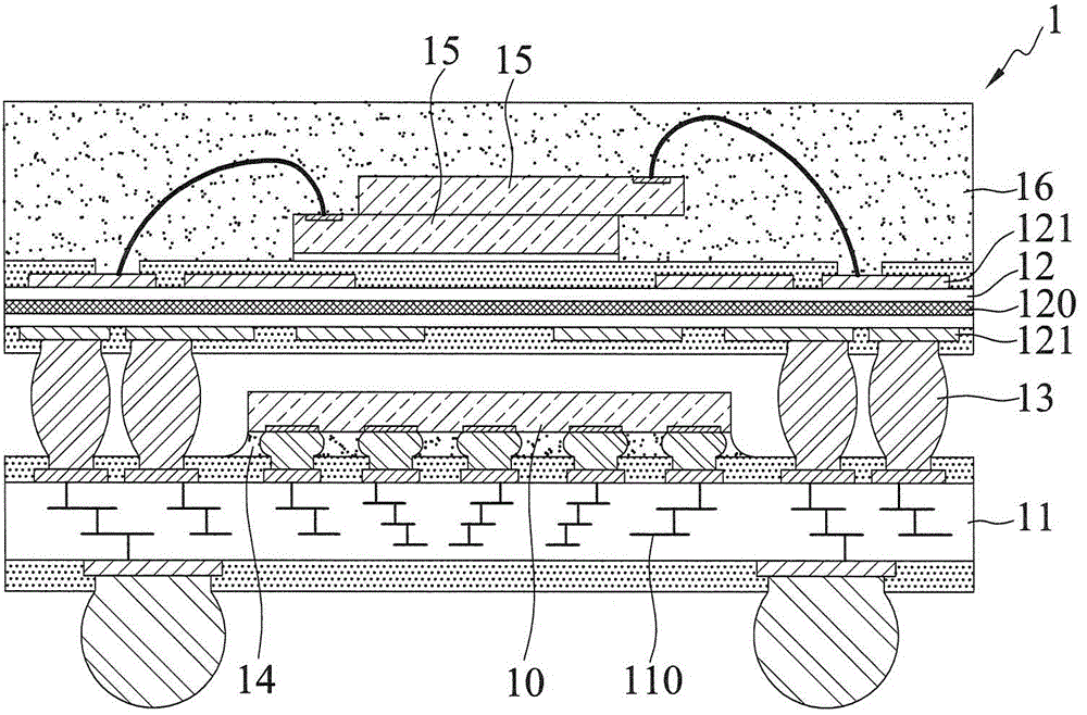
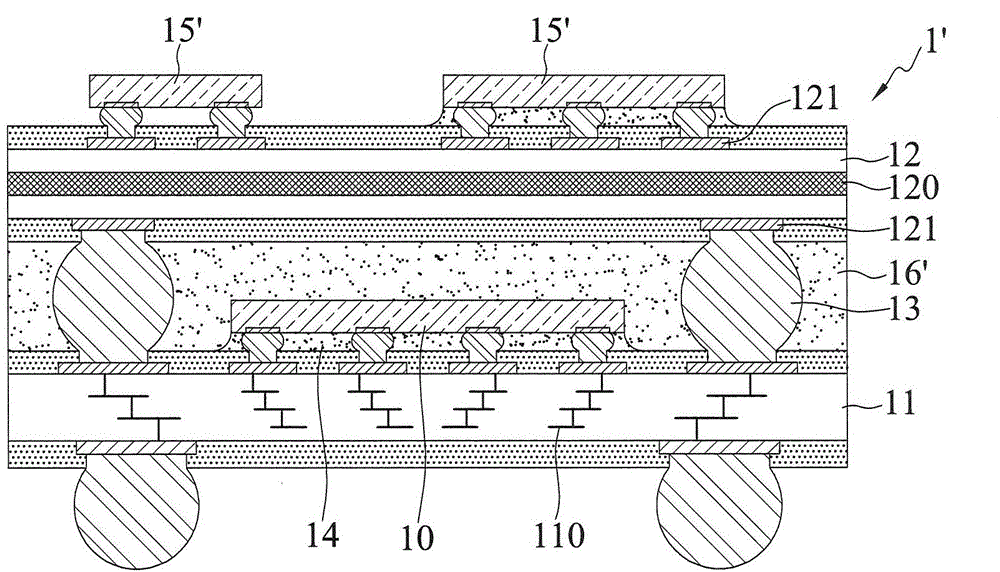
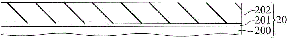
[0064] The implementation of the present invention will be described below through specific specific examples, and those skilled in the art can easily understand other advantages and effects of the present invention from the content disclosed in this specification.

[0065] It should be noted that the structures, proportions, sizes, etc. shown in the drawings attached to this specification are only used to match the content disclosed in the specification, for the understanding and reading of those skilled in the art, and are not used to limit the implementation of the present invention. Limiting conditions, so there is no technical substantive meaning, any modification of structure, change of proportional relationship or adjustment of size, without affecting the effect and purpose of the present invention, should still fall within the scope of the present invention. The disclosed technical content must be within the scope covered. At the same time, terms such as "above", "firs...


PUM


Abstract

A method for fabricating a coreless packaging substrate is provided, which includes: forming a dielectric layer on a conductive plate having a plurality of conductive pads; forming a circuit layer on the dielectric layer and forming in the dielectric layer a plurality of conductive vias that electrically connect the circuit layer and the conductive pads; and removing a portion of the conductive plate so as to cause the remaining portion of the conductive plate to form a plurality of conductive elements, thereby dispensing with a core layer and reducing the material and fabrication cost.

Description

technical field [0001] The present invention relates to a package stack structure, in particular to a package stack structure and its manufacturing method for improving product reliability. Background technique [0002] With the evolution of semiconductor packaging technology, semiconductor devices (Semiconductordevice) have developed different packaging types, and in order to improve electrical functions and save packaging space, multiple packaging structures are stacked to form a package stack structure (Package on Package, POP) , this packaging method can take advantage of the system-in-package (SiP) heterogeneous integration characteristics, and can integrate electronic components with different functions, such as: memory, central processing unit, graphics processor, image application processor, etc., through stack design to achieve system integration Integration, suitable for various thin and light electronic products. [0003] Figure 1A and Figure 1B It is a schema...

Claims


Application Information

Patent Timeline
Patent Type & Authority Applications(China)
IPC IPC(8): H01L23/498H01L21/48
CPCH01L21/48H01L23/49811H01L23/49833H01L23/5389H01L2924/181H01L2224/32225H01L2224/48091H01L2224/48227H01L2224/73204H01L2924/15311H01L23/3128H01L25/105H01L25/50H01L2224/16237H01L2924/00014H01L2924/00012H01L2224/16225H01L2924/00H01L23/5226H01L23/49822H01L21/76897H01L23/4824H01L23/3157H01L21/56
Inventor 林俊贤邱士超白裕呈沈子杰孙铭成
Owner SILICONWARE PRECISION IND CO LTD
Why Eureka
Try Eureka