Electronic device
A technology of electronic devices and circuit modules, applied in the direction of output power conversion devices, electrical components, transformer/inductor cores, etc., can solve the problems of reducing flyback transformer efficiency, electromagnetic interference, loss, etc.
- Summary
- Abstract
- Description
- Claims
- Application Information
AI Technical Summary
Problems solved by technology
Method used
Image

Examples
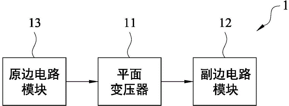
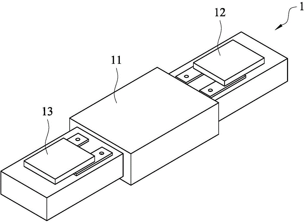
no. 1 Embodiment
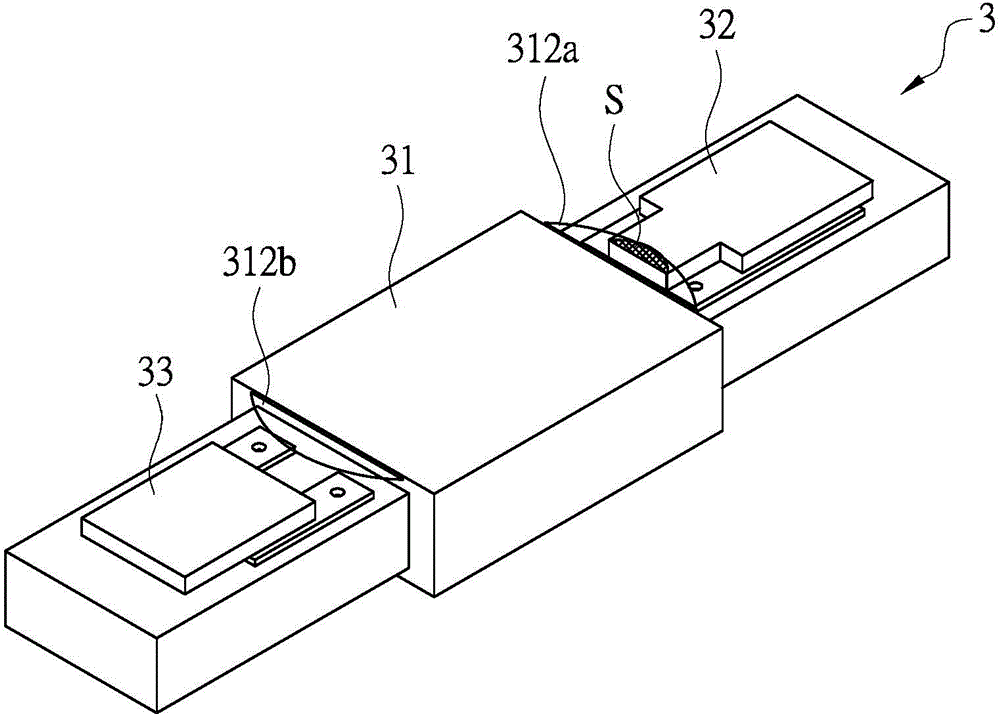
[0112] refer to Figure 3A , Figure 3B , Figure 3A A schematic structural diagram of an electronic device according to a first embodiment of the present invention is shown, Figure 3B painted Figure 3A An exploded view of the electronics shown.
[0113] Such as Figure 3A , Figure 3B As shown, the electronic device includes a magnetic component 31 (such as a transformer module), a second circuit module 32 and a first circuit module 33 .
[0114] The magnetic component 31 includes a magnetic core set 311 and a winding 312 . The magnetic core group 311 includes a first magnetic core part 311a and a corresponding second magnetic core part 311b, the first magnetic core part 311a has a magnetic core post 3111, a secondary side opening 3112, a primary side opening 3113 and magnetic core cover 3119. The winding 312 includes a second winding (such as: secondary winding, secondary winding) 312a and a first winding (such as: primary winding, primarywinding) 312b, and the win...
no. 2 Embodiment
[0122] In this embodiment, the difference between this embodiment and the first embodiment is that the vertical projection areas of the first magnetic core part 311a and the second magnetic core part 311b on the first plane do not overlap, and the first circuit module 33 or The vertical projection area of the second circuit module 32 and the magnetic core group 311 on the first plane has an overlapping portion. Please refer to Figure 4 , Figure 4An exploded view of the electronic device according to the second embodiment of the present invention is shown. There is a non-covered area on the secondary side between the vertical projection area of the first magnetic core part 311a on the first plane and the vertical projection area of the winding 312 on the first plane, while the second magnetic core part 311b is on the first plane There is a non-coverage area on the primary side between the vertical projection area of the winding 312 and the vertical projection area o...
no. 3 Embodiment
[0125] refer to Figure 5A , Figure 5B , Figure 5A An exploded view illustrating an electronic device of a third embodiment of the present invention, Figure 5B painted Figure 5A Schematic diagram of the magnetic core pack of the electronic device shown.
[0126] In this embodiment, the vertical projection area of the first magnetic core part 311a on the first plane completely covers the vertical projection area of the winding 312 on the first plane, while the vertical projection area of the second magnetic core part 311b on the first plane There is a non-covered area between the area and the vertical projection area of the winding 312 on the first plane, or the vertical projection area of the second magnetic core part 311b on the first plane completely covers the vertical projection of the winding 312 on the first plane area, and there is a non-covered area between the vertical projection area of the first magnetic core part 311a on the first plane and the ...
PUM
 Abstract
Description
Claims
Application Information
 - R&D
- Intellectual Property
- Life Sciences
- Materials
- Tech Scout
- Unparalleled Data Quality
- Higher Quality Content
- 60% Fewer Hallucinations
Browse by: Latest US Patents, China's latest patents, Technical Efficacy Thesaurus, Application Domain, Technology Topic, Popular Technical Reports.
© 2025 PatSnap. All rights reserved.Legal|Privacy policy|Modern Slavery Act Transparency Statement|Sitemap|About US| Contact US: help@patsnap.com