
Composite type high-efficiency power factor correction circuit

A power factor correction and composite technology, applied in high-efficiency power electronic conversion, output power conversion devices, electrical components, etc., can solve problems such as low power factor, affecting power grid security, large harmonic interference, etc., and achieve high power factor , high efficiency effect

Inactive Publication Date: 2015-11-25
ANHUI DONGKE SEMICON CO LTD
View PDF3 Cites 2 Cited by
  • Summary
  • Abstract
  • Description
  • Claims
  • Application Information

AI Technical Summary

Problems solved by technology

[0002] With the enhancement of global environmental awareness, the application of green and environmentally friendly power supplies will become more and more popular in countries around the world, especially in developed countries and regions. Among power supplies, switching power supplies have the highest efficiency. Conventional switching power supplies, due to the The input of the converter (AC-DC) has rectification and filter capacitors, so the PF (power factor) value of the AC is very low, generally around 0.6 to 0.8, the harmonic interference is large, and a large number of low power factor power supplies are connected to the grid. It causes the power grid to be inefficient and has a large amount of harmonic injection, which interferes with the normal operation of the power grid and affects the safety of the power grid. Therefore, most countries in the world now require power factors greater than 0.9 for switching power supplies with a power greater than 75W. , The conventional power factor correction circuit is divided into passive correction and active correction. Passive correction requires a large inductance, which consumes a lot of copper and is bulky. In order to save copper consumption and reduce the size of the power supply, the main Power factor correction circuits basically use active correction circuits, and active power factor correction circuits are mainly BOOST step-up circuits, and a small part of active power factor correction circuits use BUCK step-down circuits. Each correction circuit has its advantages and disadvantages; the advantage of BOOST step-up power factor correction circuit is high power factor, the disadvantage is that the switch tube voltage and current stress are large, the efficiency of the circuit is lower than that of BUCK circuit, and the output ripple is large; BUCK step-down power The advantages of the factor correction circuit are high efficiency, small switch tube voltage and current stress, and small output ripple. The disadvantage is that the power factor is lower than that of the BOOST circuit, and when the input voltage is lower than the output voltage, the circuit cannot work.

Method used


Image

  • Composite type high-efficiency power factor correction circuit
  • Composite type high-efficiency power factor correction circuit
  • Composite type high-efficiency power factor correction circuit

Examples


Embodiment

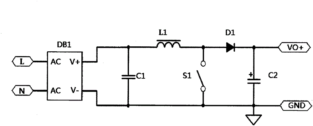
[0024] This embodiment provides a composite high-efficiency power factor correction circuit, including an AC input circuit, a rectifier circuit DB1, an inductor L1, two freewheeling diodes, two electronic switches and two capacitors; the two freewheeling diodes are respectively are the first freewheeling diode D1 and the second freewheeling diode D2; the two electronic switches are the first electronic switch S1 and the second electronic switch S2 respectively; the two capacitors are the high frequency capacitor C1 and the filter capacitor C2 respectively .

[0025] The output end of the AC input circuit is electrically connected to the input end of the rectification circuit DB1; the output end of the rectification circuit DB1 is connected to a high-frequency capacitor C1 for filtering out high-frequency interference in the power grid; the rectification circuit The positive pole of the output end of DB1 is connected to one pole of the first electronic switch S1, and the other ...


PUM


Abstract

The invention discloses a composite type high-efficiency power factor correction circuit which comprises an alternating current input circuit, a rectification circuit, at least one inductor, two flywheel diodes, two electronic switches and two capacitors. The composite type high-efficiency power factor correction (PFC) circuit has the advantages of high efficiency of a BUCK type correction circuit, low output ripple and small voltage and current stress of a switching tube and also has the advantages of high power factor of a BOOST type correction circuit, and moreover, the composite type high-efficiency PFC circuit shares the same inductor and is an economic and high-efficiency PFC correction circuit.

Description

technical field [0001] The present invention relates to a power factor correction (PFC) circuit of an AC-to-DC conversion circuit, in particular to a combined circuit using BUCK step-down and BOOST step-up PFC, which improves the efficiency of the circuit and reduces the voltage of the switch tube and the current stress, reducing the output ripple current. Background technique [0002] With the enhancement of global environmental awareness, the application of green and environmentally friendly power supplies will become more and more popular in countries around the world, especially in developed countries and regions. Among power supplies, switching power supplies have the highest efficiency. Conventional switching power supplies, due to the The input of the converter (AC-DC) has rectification and filter capacitors, so the PF (power factor) value of the AC is very low, generally around 0.6 to 0.8, the harmonic interference is large, and a large number of low power factor pow...

Claims


Application Information

Patent Timeline
Patent Type & Authority Applications(China)
IPC IPC(8): H02M1/42
CPCY02B70/10Y02P80/10
Inventor 谢勇
Owner ANHUI DONGKE SEMICON CO LTD
Learn More