
Device for conserving power in a piston compressor

A power-saving, compressor technology, applied in piston pumps, mechanical equipment, machines/engines, etc., can solve the problems of lubricating oil concentration, affecting compressor efficiency, etc., to achieve the effect of power saving and power saving optimization

Inactive Publication Date: 2015-11-25
KNORR BREMSE SYST FUER NUTZFAHRZEUGE GMBH
View PDF7 Cites 0 Cited by
  • Summary
  • Abstract
  • Description
  • Claims
  • Application Information

AI Technical Summary

Problems solved by technology

Due to the reduced pressure level in the compression chamber in the idling position, even in this type of design there is the problem that the lubricating oil goes up the piston ring, ie it can reach the compression chamber and therefore there is air in the lubricating oil thicken
In addition, throttling losses occur due to the non-return cover, which adversely affects the efficiency of the compressor

Method used


Image

  • Device for conserving power in a piston compressor
  • Device for conserving power in a piston compressor
  • Device for conserving power in a piston compressor

Examples


Embodiment Construction

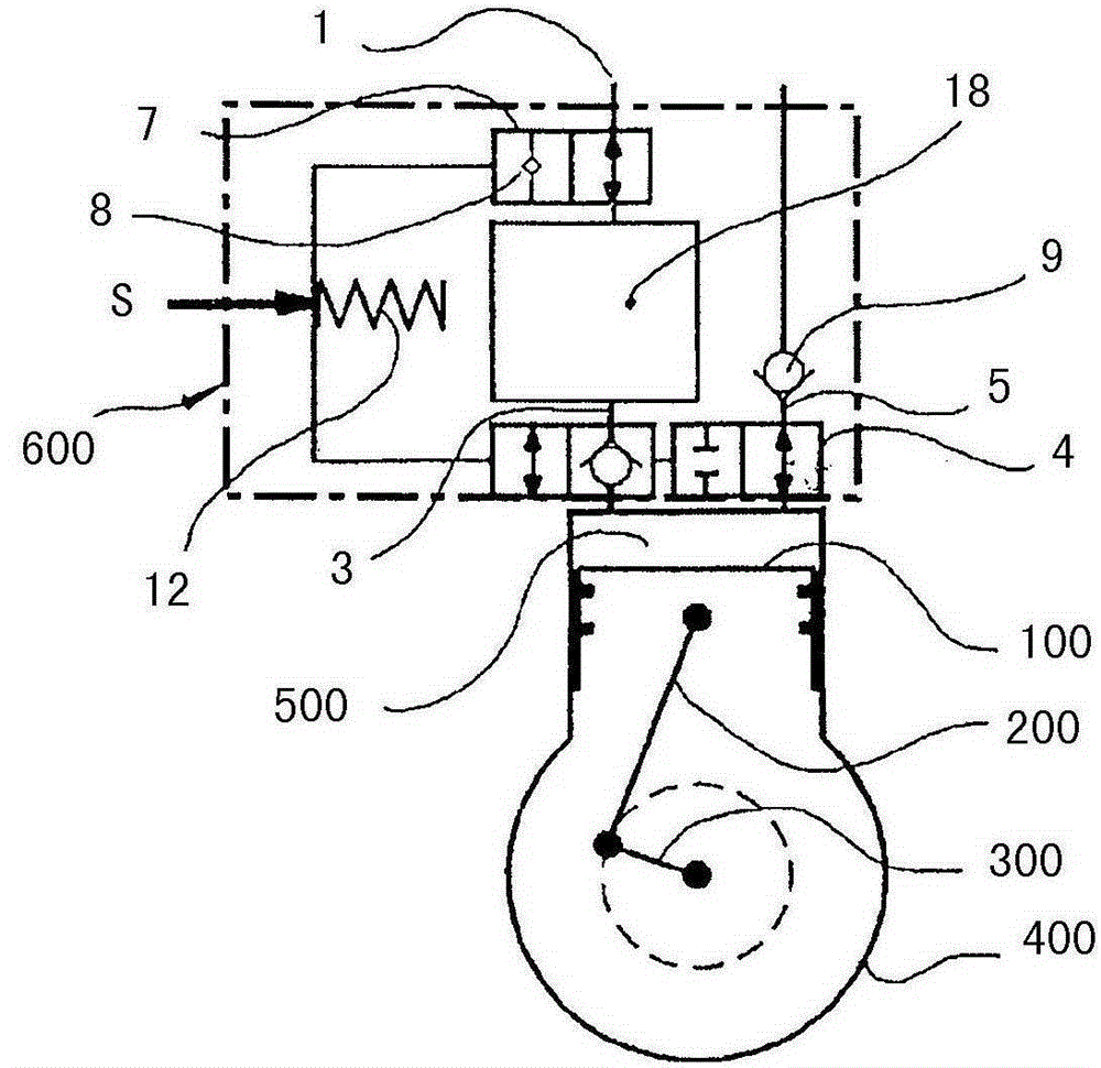
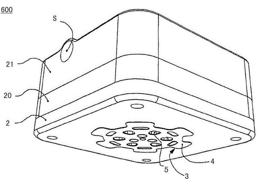
[0033] according to figure 1 , a piston compressor for generating compressed air basically comprises a piston 100 articulated to a driven crankshaft 300 via a connecting rod 200 . Crankshaft 300 is rotatably supported in crankcase 400 . The crankcase 400 comprises a cylinder which together with the piston 100 forms a compression chamber 500 which is provided at the end with a cylinder head 600 which is only schematically shown here and which has a power-saving lever integrated into the cylinder head. installation.

[0034] The cylinder head 600 comprises a slide 7 with an integrated minimum air valve 8 which acts as a 2 / 2-way valve and controls the suction connection 1 of the piston compressor. The ambient air sucked in via the suction connection 1 passes via the slide 7 in the cylinder head 600 to the suction chamber 18 which is formed in the cylinder head and serves as a connectable clearance space. In the direction of the compression chamber 500 , the suction chamber 18 ...


PUM


Abstract

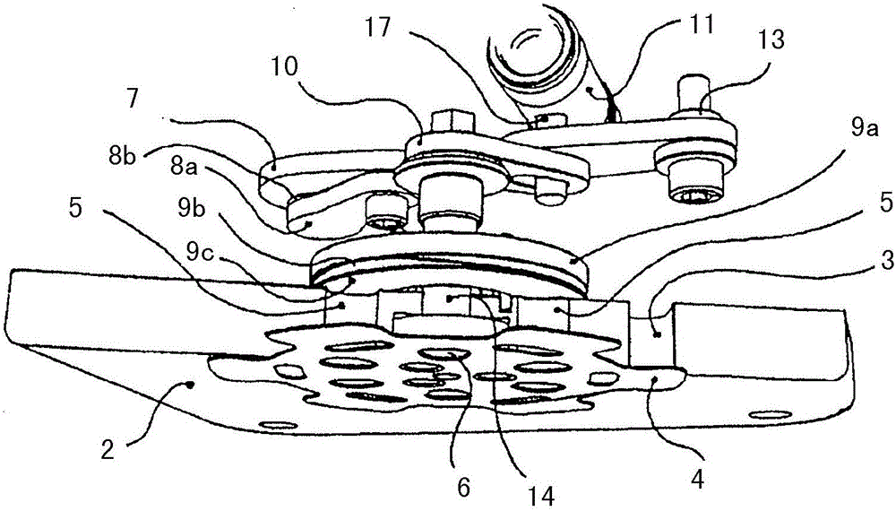
The invention relates to a device for conserving power in a piston compressor, in particular for generating compressed air in a motor vehicle, having a piston (100) delimiting a compression chamber (500) for generating compressed air, which, originating from the ambient environment, arrives in the compression chamber (500) for compression by way of at least one suction connection (1) formed on a cylinder head cover (21) and an intake valve array arranged on a valve plate (2). For the purpose of conserving power, a pressure-dependently acting idling device is provided for the intake valve array having a dedicated suction lamella (4), which can be rotated by actuating means between a working position overlapping at least one suction opening (3) and an idling position unblocking, at least in part, the at least one suction opening (3). The invention is characterized in that the actuating means actuate the suction lamella (4) in a coordinated manner such that in the idling position, the section lamella (4) unblocks the at least one suction opening (3) in the valve plate (2), at least partially, while simultaneously blocking adjacent pressure valve cross-sections (5), at least partially, and locking the suction connection (1) at the cylinder head cover (21) by means of a slider (7) in order to form an increased harmful space in the area of the cylinder head (600).

Description

technical field [0001] The invention relates to a device for saving power in a piston compressor, in particular for generating compressed air in a motor vehicle, which device has a piston arranged axially movable in a cylinder for generating compression Air, which enters the compression chamber of the cylinder for compression via at least one intake valve, wherein the intake valve cooperates with a pressure-controlled means for saving power. [0002] The field of application of the invention extends mainly to reciprocating piston compressors used in motor vehicle construction, in particular commercial vehicle construction, which are primarily used to generate compressed air for compressed air systems in motor vehicles. Background technique [0003] Devices for saving power are generally known for regulating the delivery rate of such piston compressors and for regulating the pressure in downstream consumers, for example the pressure in a brake system. The device for saving p...

Claims


Application Information

Patent Timeline
Patent Type & Authority Applications(China)
IPC IPC(8): F04B49/16F04B49/24
CPCF04B49/16F04B49/243F04B7/0061F04B7/0007F04B7/0046F04B39/08F04B39/1073F04B49/225
Inventor J·迈拉尔
Owner KNORR BREMSE SYST FUER NUTZFAHRZEUGE GMBH
Learn More