Eureka AIR delivers breakthrough ideas for toughest innovation challenges, trusted by R&D personnel around the world.

Novel use of bismuth fluoride

A technology of bismuth fluoride and photocatalyst, applied in the application field of bismuth fluoride in photocatalyst, can solve problems such as electronic transition, and achieve the effect of expanding types

Inactive Publication Date: 2015-12-02
NANJING UNIV OF INFORMATION SCI & TECH
View PDF2 Cites 2 Cited by
  • Summary
  • Abstract
  • Description
  • Claims
  • Application Information

AI Technical Summary

Problems solved by technology

Semiconductor photocatalysis is a very promising technology to solve the above problems. Since Fujishima et al. (Fujishima, et al. Nature, 1972) reported TiO2 photocatalyst in 1972, photocatalysis technology has developed rapidly, but the bandgap width of TiO2 reaches 3.2eV , making it impossible for electrons to transition under visible light

Method used


Image

  • Novel use of bismuth fluoride
  • Novel use of bismuth fluoride
  • Novel use of bismuth fluoride

Examples


Embodiment Construction

[0010] The present invention will be described in detail below in conjunction with specific embodiments.

[0011] Preparation of bismuth fluoride:

[0012] In a water bath at 80°C, take 40mL of water, pour it into a beaker, add 0.485g of bismuth nitrate under stirring conditions, then add 0.108g of ammonium fluoride, stir well, and finally add 5ml of 0.01mol / L ammonia water, and stir for 3h , centrifuged to wash the precipitate, and then dried.

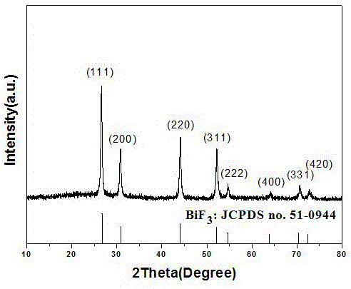
[0013] Product identification: Compared with the XRD standard card ((JCPDS:51-0944), the obtained product is bismuth fluoride, such as image 3 shown.

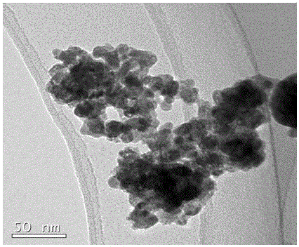
[0014] Such as figure 1 The scanning electron microscope picture of the obtained bismuth fluoride is shown, and it can be seen from the figure that the bismuth fluoride crystal particles prepared by the present invention are at the nanometer level.

[0015] Photocatalytic experiments were carried out on the prepared bismuth fluoride crystal particles:

[0016] In the photocatalyt...


PUM


Abstract

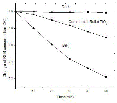
The invention discloses a novel use of bismuth fluoride. Bismuth fluoride is used in a photocatalyst. Nanometer bismuth fluoride crystal particles have a rhodamine B degradation rate under UV irradiation faster than that of commercial TiO2 and increase types of photocatalysts.

Description

technical field [0001] The invention relates to a new application of bismuth fluoride, in particular to the application of bismuth fluoride in photocatalyst. Background technique [0002] With the development of social processes, energy shortages and environmental pollution have become increasingly serious, and it is imperative to establish a sustainable society. Semiconductor photocatalysis is a very promising technology to solve the above problems. Since Fujishima et al. (Fujishima, et al. Nature, 1972) reported TiO2 photocatalyst in 1972, photocatalysis technology has developed rapidly, but the bandgap width of TiO2 reaches 3.2eV , making it impossible for electrons to transition under visible light. In order to make better use of visible light, exploring new photocatalysts is a practical way. Contents of the invention [0003] The purpose of the present invention is to provide a new photocatalyst in order to solve the defects in the prior art. [0004] In order to a...

Claims


Application Information

Patent Timeline
Patent Type & Authority Applications(China)
IPC IPC(8): B01J27/12
Inventor 滕飞俸晨凯邹思佳刘再伦王淑蓉陈敏东
Owner NANJING UNIV OF INFORMATION SCI & TECH
Why Eureka
Eureka Blog
Learn More