
Lifting and pressing pin control device of sewing machine

A control device and presser foot lifting technology, which is applied in the direction of sewing machine control devices, sewing machine components, sewing equipment, etc., can solve the problems of labor-saving manual operation of the presser foot lifter, and achieve the effect of increasing work efficiency, reducing labor intensity, and simple work

Inactive Publication Date: 2015-12-02
ZHEJIANG ZOJE SEWING MACHINE
View PDF1 Cites 9 Cited by
  • Summary
  • Abstract
  • Description
  • Claims
  • Application Information

AI Technical Summary

Problems solved by technology

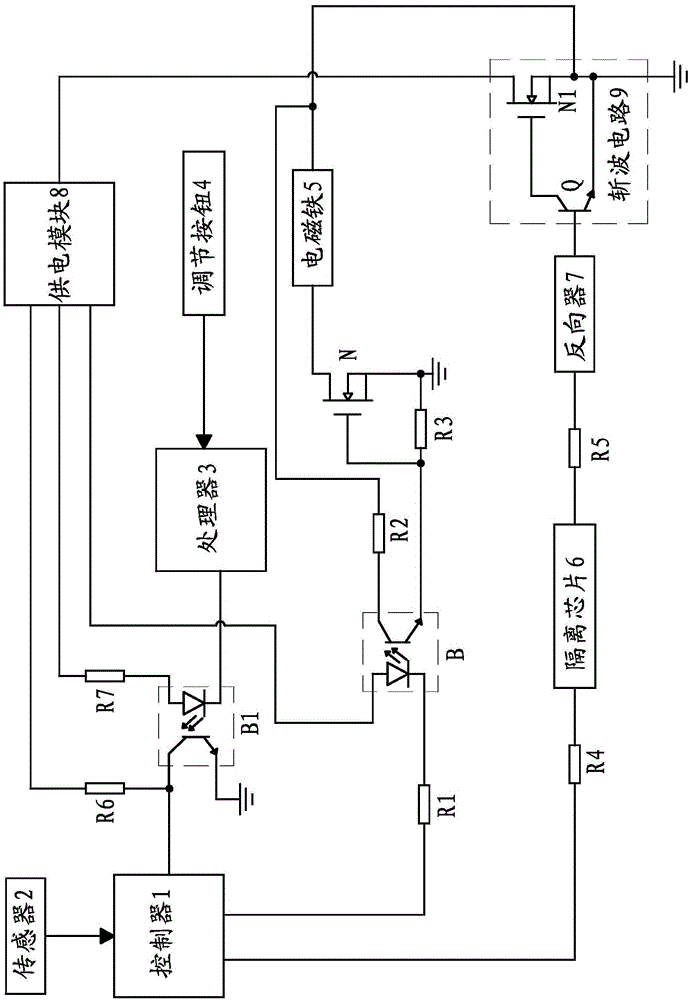
[0006] Aiming at the above-mentioned problems in the existing technology, the present invention proposes a sewing machine presser foot lifting control device. The technical problem to be solved by the control device is how to make the manual operation of the presser foot lifting labor-saving

Method used


Image

  • Lifting and pressing pin control device of sewing machine
  • Lifting and pressing pin control device of sewing machine
  • Lifting and pressing pin control device of sewing machine

Examples


Embodiment 1

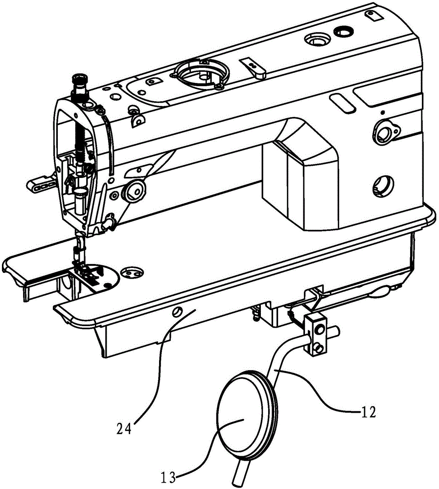
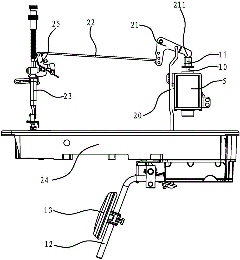
[0031] Such as Figures 2 to 5 As shown, the sewing machine includes a presser foot 23, a rear lever 21, a manipulator for manually lifting the presser foot 23 and an electromagnet 5 for automatically lifting the presser foot 23, and the manipulator and electromagnet 5 can drive the rear lever 21 to make the presser foot 23 moves. Back lever 21 connects presser foot 23 by pull bar 22 and front lever 25, and pull bar 22 one end connects back lever 21, and the other end connects front lever 25, and front lever 25 connects presser foot 23.

[0032] The electromagnet 5 has a telescopic push rod 10 up and down, the upper end of the push rod 10 is screwed with a push nut 11, the upper end surface of the push nut 11 is a straight and smooth push surface, and the rear end of the rear lever 21 has The abutting portion 211 protrudes downward in an arc shape, and the abutting portion 211 of the rear lever 21 abuts against the pushing surface of the pushing nut 11 .

[0033] The preferr...

Embodiment 2

[0052] The structure and working process in this embodiment are basically the same as those in Embodiment 1, the difference in structure is that the sensor 2 is a position sensor.

[0053] Its working process is different in that:

[0054]The position sensor is used to detect the amount of change in the position of the manipulator and send the signal to the controller 1, and the controller 1 outputs a corresponding control signal to the electromagnet control circuit according to the signal sent by the position sensor, and the electromagnet control circuit controls the operation of the electromagnet 5, Working power is less than the power of electromagnet 5 when automatic presser foot lifter 23 works.

[0055] When the operator manually lifts the presser foot with his knee against the control panel 13, the sensor 2 detects the position change of the control panel 13 and can obtain the position change of the control panel 13, and send the detected position of the control panel 1...


PUM


Abstract

The invention provides a lifting and pressing pin control device of a sewing machine and belongs to the technical field of sewing machines. The lifting and pressing pin control device of the sewing machine solves the problem that a lifting and pressing pin in the prior art is troublesome to operate manually. The lifting and pressing pin control device of the sewing machine comprises a controller, an electromagnet control circuit used for controlling the work power of an electromagnet, and a sensor used for detecting the change of the position of an operating part, the sensor is connected with the input end of the controller, the electromagnet control circuit is connected with the output end of the controller, the output end of the electromagnet control circuit is connected with the electromagnet, the controller outputs a control signal to the electromagnet control circuit when receiving a signal transmitted by the sensor, and the electromagnet control circuit controls the electromagnet to work with the power smaller than the power of the electromagnet when an automatic lifting and pressing pin works. The lifting and pressing pin control device makes labor saved when the lifting and pressing pin is manually operated.

Description

technical field [0001] The invention belongs to the technical field of sewing machines, and relates to a presser foot lifting control device of a sewing machine. Background technique [0002] A sewing machine is a machine that uses one or more sewing threads to form one or more stitches on the sewing material, and is a machine that interweaves or sews one or more layers of sewing materials. The working process of the sewing machine needs to lift the presser foot of the sewing machine. At present, the sewing machine has two modes of operation, manual and automatic, to lift the presser foot. The manual presser foot lift method is to manually drive the corresponding manual transmission mechanism to lift the presser foot, and the automatic presser foot lift method uses electric components such as electromagnets, motors, etc. as power sources to drive the corresponding automatic transmission mechanism to lift the presser foot. [0003] A separate manual or automatic presser foot...

Claims


Application Information

Patent Timeline
Patent Type & Authority Applications(China)
IPC IPC(8): D05B29/02
CPCD05B29/02D05B69/10
Inventor 卢孔贵楼俏军马光涛林智宝李宗润蒋陈静
Owner ZHEJIANG ZOJE SEWING MACHINE
Learn More