Configuration of hydraulic element of excavator

A technology for hydraulic components and excavators, which is applied to mechanically driven excavators/dredgers, earth movers/shovels, construction, etc., and can solve unreasonable internal oil passage design, large leakage, and large pressure loss, etc. problems, achieve the effect of optimizing the internal oil passage design, reducing energy waste and prolonging the service life

Pending Publication Date: 2015-12-02
SHANDONG CHANGLIN MACHINERY GRP
View PDF0 Cites 2 Cited by
  • Summary
  • Abstract
  • Description
  • Claims
  • Application Information

AI Technical Summary

Problems solved by technology

The matching of hydraulic components and the whole machine is a key point affecting the performance of the excavator, including the operability, efficiency and fuel consumption of the action, but in the existing hydraulic system configuration, the displacement of the pump is relatively small in the excavator of the same tonnage , in actual work, the power of the engine cannot be effectively utilized, resulting in slow efficiency; most of the slewing motors are driven by a single motor, which makes the starting torque of the excavator too small, resulting in slow starting speed and slow braking when stopping. The offset angle of the excavator is large, and the meshing area of ​​the single slewing reducer and the excavator ring gear is small, resulting in short life, which is not conducive to the precise operation of the excavator and the improvement of efficiency
In addition, the spool diameter of the hydraulic main control valve is small, the rated flow rate is small, and the pressure loss is large. At the same time, due to the unreasonable design of the internal oil passage, the leakage is too large, resulting in a waste of energy

Method used


Image

  • Configuration of hydraulic element of excavator

Examples


Embodiment Construction

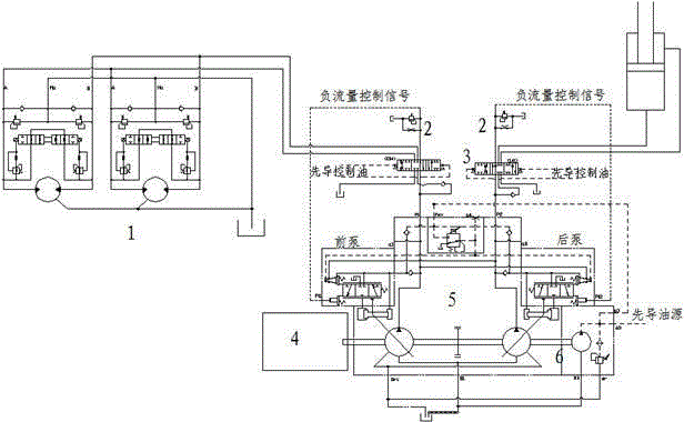
[0013] The present invention will be further described below in conjunction with the accompanying drawings and specific embodiments.

[0014] An excavator hydraulic component configuration, including a main pump 5, a swing motor 1 and a main control valve 3, the main pump 5 is connected to the engine 4 through the spline of the main shaft, and the main pump 5 and the main control valve 3 are connected through hydraulic pipelines The working oil port of the main control valve 3 is connected with the large and small cavities of each oil cylinder port of the excavator, the oil inlet and outlet ports of the rotary motor 1 and the travel motor, and the rotary motor 1 is a double rotary motor. The main pump 5 is a negative control series pump to provide working oil, with a displacement of 200ml / r; the rotary motor 1 is a fixed displacement dual motor with a displacement of 170ml / r; the main control valve 3 is a negative flow control valve, and the valve The core diameter is 34mm, th...


PUM


Abstract

The invention discloses configuration of a hydraulic element of an excavator. The configuration comprises a main pump, a rotary motor and a main control valve. The main pump is connected with an engine through a spline of a main shaft. The main pump is connected with the main control valve through a hydraulic pipeline. A work oil opening of the main control valve is connected with large cavities and small cavities of all oil cylinder openings of the excavator and oil inlet and return openings of the rotary motor and a walking motor, and the rotary motor is a double rotary motor. The double rotary motor is adopted, displacement and starting torque are large, and when the excavator rotates, time consumed from a static state to a constant speed state is short, and work efficiency is greatly improved. Meanwhile, the contact area of the double rotary motor and a gear ring of the excavator is large, the borne unit area is small, and the service life of the excavator can be greatly prolonged. Internal oil channel design is optimized, the sealing mode of a one-way valve and the like is changed, so that the leakage amount becomes small, and energy waste is reduced.

Description

technical field [0001] The invention belongs to the field of engineering machinery hydraulic transmission, in particular to an excavator hydraulic component configuration. Background technique [0002] Hydraulic excavator is a kind of widely used engineering machinery, which is widely used in engineering construction. The matching of hydraulic components and the whole machine is a key point affecting the performance of the excavator, including the operability, efficiency and fuel consumption of the action, but in the existing hydraulic system configuration, the displacement of the pump is relatively small in the excavator of the same tonnage , in actual work, the power of the engine cannot be effectively utilized, resulting in slow efficiency; most of the slewing motors are driven by a single motor, which makes the starting torque of the excavator too small, resulting in slow starting speed and slow braking when stopping. The offset angle of the excavator is relatively larg...

Claims


Application Information

Patent Timeline
Patent Type & Authority Applications(China)
IPC IPC(8): E02F9/22E02F3/42
Inventor 巩秀江郇庆祥袁青照刘军耿伟许跃雷
Owner SHANDONG CHANGLIN MACHINERY GRP
Why Eureka
Try Eureka